EPSON Stylus COLOR 860/1160
Revision C
Disassembly and Assembly
Disassembly Procedures
94
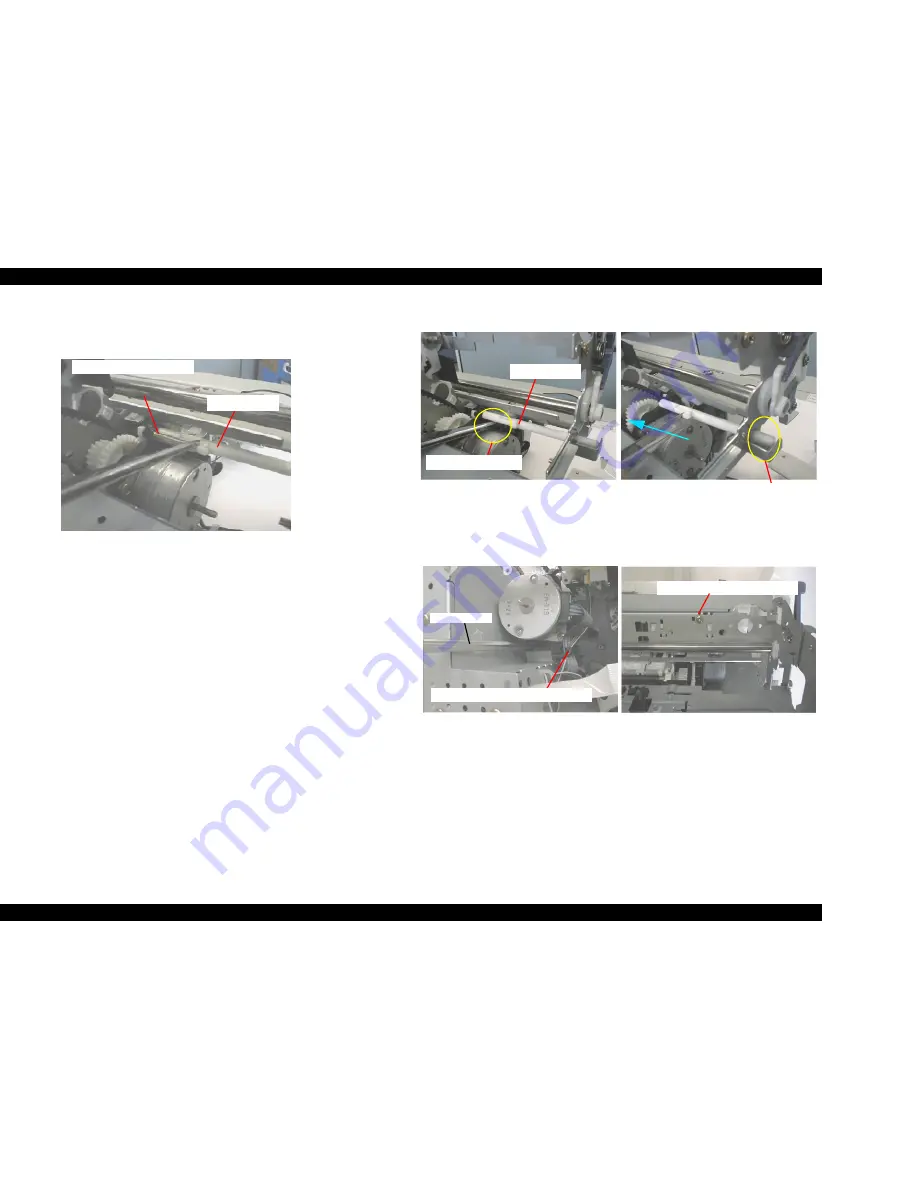
7) Remove the Torsion Spring 0.618 between DE Lock Lever and the hook
on the DE unit. Refer to Figure 4-22.
Figure 4-22. Removing the Tension Spring 0.618
8) Push down the hook on the DE unit carefully and slide the DE Lock Lever
until it touches the right frame. The left end of the DE Lock lever comes off
the hole (for DE Lock Lever) in the DE unit.
Refer to Figure 4-23.
9) Pull the left edge of the DE Lock Lever to your side slightly and slide it to
the left carefully to remove the DE Lock Lever from the hole in the Top
Frame. Refer to Figure 4-23.
10) Remove two screws (No.1 & No. 3) securing the DE unit.
Refer to Figure 4-24.
n
No.1 Screw: Securing the DE Unit to the Middle Frame.
n
No. 2 Screw: Securing the DE unit to the Top Frame.
Figure 4-23. Removing the DE Lock Lever
Figure 4-24. Removing the DE Assembly
Torsion Spring 0.618
DE Lock Lever
DE Lock Lever
Hook on the DE Unit
Fixing the hole in
the Top Frame
No. 2 Screw on the Top Frame
Screw driver
No. 1 Screws on the Middle Frame
Summary of Contents for Stylus COLOR 1160
Page 8: ...C H A P T E R PRODUCTDESCRIPTION ...
Page 28: ...C H A P T E R OPERATINGPRINCIPLES ...
Page 53: ...C H A P T E R TROUBLESHOOTING ...
Page 74: ...C H A P T E R DISASSEMBLYANDASSEMBLY ...
Page 116: ...C H A P T E R ADJUSTMENT ...
Page 150: ...C H A P T E R MAINTENANCE ...
Page 160: ...APPENDIX C H A P T E R ...


