EPSON Stylus Color 400 Service Manual
Rev. A
1-27
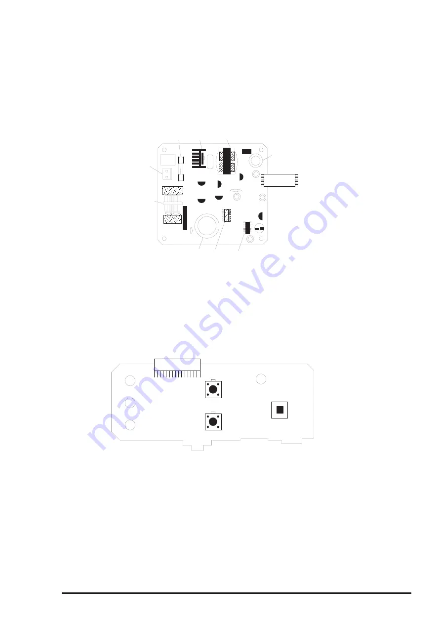
1.8.3 C206 PSB/PSE Power Supply Board
In the electric boards for Stylus Color 400, switching regulator method is used and supplies
stable logic and power voltages constantly. Also, since this C206PSB board has secondly type
switch for its circuit system, it is possible to keep supplying electricity to the C206 main control board
for 30 seconds even after the power switch is turned off.
Using this time difference, even when mis-operation is done by the user such as turning off the power
during the middle of printing work, it prevents thickened ink from attaching around the nozzle plate
by transferring the head to cap position.
1.8.4 C206PNL(Panel) Board
Panel board (C206 PNL board) is located in the panel case where is in the right bottom of the front
printer and consists of 3 switches, 4 LEDs and 1 connector.
Trans (T1)
Q1 (FET)
CN2
CN1
Fuse (F1)
C11
PC1
Filter (L1)
IC51
C51
Figure 1-12. Exterior of C206 PSB/PSE Board
Figure 1-13. Exterior of C206 PNL Board
Summary of Contents for Stylus Color 400
Page 5: ...REVISION SHEET Revision Issued Data Contents Rev A February18 1997 First issue ...
Page 126: ...Chapter 6 Maintenance Rev A 6 5 No 1 No 2 10mm 2mm 2mm No 3 No 11 GEAR 34 ...
Page 138: ...EPSON Stylus Color400 Service Manual Rev A A 9 Figure A 3 C206 PSB Board Component Layout ...
Page 139: ...Appendix Rev A A 10 Figure A 4 C206 PSE Board Component Layout ...
Page 140: ...EPSON Stylus Color400 Service Manual Rev A A 11 Figure A 5 C206 PNL Component Layout ...
Page 141: ...Appendix Rev A A 12 A 5 Exploded Diagrams Figure A 6 Stylus Color 400 Exploded Diagram 1 ...
Page 143: ...Appendix Rev A A 14 Figure A 8 Stylus Color 400 Exploded Diagram 3 ...
Page 145: ...EPSON SEIKO EPSON CORPORATION ...


