EPSON Stylus Color 400 Service Manual
Rev.A
2-14
2.1.1.4 Ink System
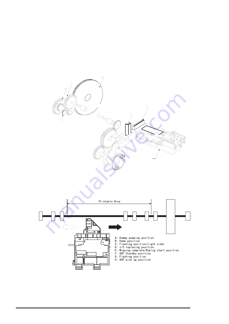
Ink system mechanism consists of 1)cap mechanism, 2)pump mechanism, 3)carriage lock
mechanism, 4)waste ink absorber and 5)ink sequence. Out of these mechanism, from 1) to 4)
are physical mechanism and parts which are mounted on the printer mechanism and 5) ink
sequence is performed automatically by firmware. Also, unlike previous models, since
Stylus Color 400 has no engage/disengage mechanism to change over pump mechanism and
paper feed mechanism, it is one of the major characteristics that pump and platen are always
at work whenever the PF motor is driven. The figure below shows head positions when the ink
system and various ink sequence are performed.
Head Cleaner
Carriage Lock
Pump Roller
Cap Unit
Platen Drive Gear
Eject Roller Drive Gear
Eject Roller
Trasmission Gear
PF(Pump) Motor Pinion
Figure 2-12.Ink System Mechanism
A
B
C
D
E
F
G
H
CRHP
2975 dot
Figure2-13. Major Ink Sequence Position on the Carriage Mechanism
Summary of Contents for Stylus Color 400
Page 5: ...REVISION SHEET Revision Issued Data Contents Rev A February18 1997 First issue ...
Page 126: ...Chapter 6 Maintenance Rev A 6 5 No 1 No 2 10mm 2mm 2mm No 3 No 11 GEAR 34 ...
Page 138: ...EPSON Stylus Color400 Service Manual Rev A A 9 Figure A 3 C206 PSB Board Component Layout ...
Page 139: ...Appendix Rev A A 10 Figure A 4 C206 PSE Board Component Layout ...
Page 140: ...EPSON Stylus Color400 Service Manual Rev A A 11 Figure A 5 C206 PNL Component Layout ...
Page 141: ...Appendix Rev A A 12 A 5 Exploded Diagrams Figure A 6 Stylus Color 400 Exploded Diagram 1 ...
Page 143: ...Appendix Rev A A 14 Figure A 8 Stylus Color 400 Exploded Diagram 3 ...
Page 145: ...EPSON SEIKO EPSON CORPORATION ...


