EPSON Stylus Color 400 Service Manual
Rev. A
3-4
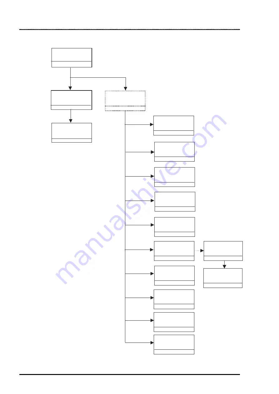
3.2 Disassembly Procedures
The figure below shows procedures for disassembly.
Remove
the Housing
3.2.1
Remove
the Board Assembly
3.2.2
Remove the
operation panel
3.2.3
Remove the Printer
Mechanism
3.2.4
Refer to
Remove
the Print Unit
3.2.4.1
Remove
the Absorber tray,
Assembly;A
3.2.4.2
Remove the Pump
Assembly,
Cap Assembly
3.2.4.3
Remove the CR
Motor Assembly
3.2.4.4.
Remove the PF
Motor Assembly
3.2.4.5
Remove the ASF
Assembly
3.2.4.6
Remove the CR
Assembly
3.2.4.7
Remove the PF
Roller Assembly
3.2.4.8
Remove the PE
Paper Detector
Assembly
3.2.4.9
Remove the HP
Detector
3.2.4.10
Remove the LD
Roller Assembly
(Right/Left)
3.2.4.6.2
Remove the Paper
Feed Roller
Assembly
3.2.4.6.1
Figure 3-1. Flow Chart of Disassembly
Summary of Contents for Stylus Color 400
Page 5: ...REVISION SHEET Revision Issued Data Contents Rev A February18 1997 First issue ...
Page 126: ...Chapter 6 Maintenance Rev A 6 5 No 1 No 2 10mm 2mm 2mm No 3 No 11 GEAR 34 ...
Page 138: ...EPSON Stylus Color400 Service Manual Rev A A 9 Figure A 3 C206 PSB Board Component Layout ...
Page 139: ...Appendix Rev A A 10 Figure A 4 C206 PSE Board Component Layout ...
Page 140: ...EPSON Stylus Color400 Service Manual Rev A A 11 Figure A 5 C206 PNL Component Layout ...
Page 141: ...Appendix Rev A A 12 A 5 Exploded Diagrams Figure A 6 Stylus Color 400 Exploded Diagram 1 ...
Page 143: ...Appendix Rev A A 14 Figure A 8 Stylus Color 400 Exploded Diagram 3 ...
Page 145: ...EPSON SEIKO EPSON CORPORATION ...


