Chapter4 Adjustment
Rev. A
4-1
4.1 Overview
This section describes adjustments required when the printer is disassembled and assembled after repair.
4.1.1 Required Adjustments
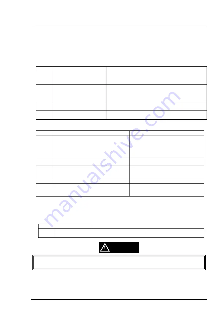
Stylus Color 400 has following required adjustments.(Refer to table 4-1) Refer to figures for the actual
procedure and perform appropriate adjustment for each exchanged unit.
No.
Adjustment Item
Conditions
1
Parallel Adjustment
•
When you exchange or remove the Carriage guide shaft.
•
When you move the parallelism adjustment bush.
2
Initial ink charge
•
When you exchange or remove the print head.
3
VH voltage Writing Operation
•
When you exchange or remove the print head.
•
When you exchange the C206 main board.
Note)
The values of address are not lost by EEPROM reset
operation.
4
Printing Head Angle Adjustment
•
When you exchange or remove the print head.
•
When you move the head adjustment lever.
5
Bi-D adjustment
•
When you exchange or remove the print head.
•
When you exchange the C206 main board.
No.
Content of Operation
Adjustment Procedure
1
Exchange or Removal of Print head
1)Perform Vh voltage writing operation.
(Only when the print head is exchanged)
2)Perform initial ink charge.
3)Perform print head angle adjustment.
4)Perform Bi-d Adjustment.
2
Exchange of C206 Main Board
1)Perform Vh voltage writing operation.
2)Perform Bi-d adjustment.
3
Exchange or Removal of Carriage Unit
1)Perform parallel adjustment.
2)Perform print head angle adjustment.
3)Perform Bi-d adjustment.
4
Exchange of CR Motor
1)Perform Bi-d adjustment.
5
Exchange of Printer Mechanism
1)Perform Vh voltage writing operation.
2)Perform initial ink charge.
3)Perform Bi-d adjustment.
4.1.2 Required Adjustment Tools
The table4-3 below shows adjustment tools for Stylus Color 400.
Table 4-3. Adjustment Tools for Stylus Color 400
No.
Name
Adjustment item
Content/Specification
1
Thickness Gage
Parallel Adjustment
Thickness=1.1mm(1.04mm)
2
Adjustment Program
Each Mechanism Settings
Exclusive Program(“J80C10E”)
CAUTION
Never use the bent (curved or tilted)or rusty thickness gage.
Erase any dirt, grease or obstacles on the thickness gage before you use it.
Table 4-1. Required Adjustment and Contents
Table 4-2. Operation and Adjustment Item
Summary of Contents for Stylus Color 400
Page 5: ...REVISION SHEET Revision Issued Data Contents Rev A February18 1997 First issue ...
Page 126: ...Chapter 6 Maintenance Rev A 6 5 No 1 No 2 10mm 2mm 2mm No 3 No 11 GEAR 34 ...
Page 138: ...EPSON Stylus Color400 Service Manual Rev A A 9 Figure A 3 C206 PSB Board Component Layout ...
Page 139: ...Appendix Rev A A 10 Figure A 4 C206 PSE Board Component Layout ...
Page 140: ...EPSON Stylus Color400 Service Manual Rev A A 11 Figure A 5 C206 PNL Component Layout ...
Page 141: ...Appendix Rev A A 12 A 5 Exploded Diagrams Figure A 6 Stylus Color 400 Exploded Diagram 1 ...
Page 143: ...Appendix Rev A A 14 Figure A 8 Stylus Color 400 Exploded Diagram 3 ...
Page 145: ...EPSON SEIKO EPSON CORPORATION ...


