Chapter4 Adjustment
Rev. A
4-3
Left Side
Right Side
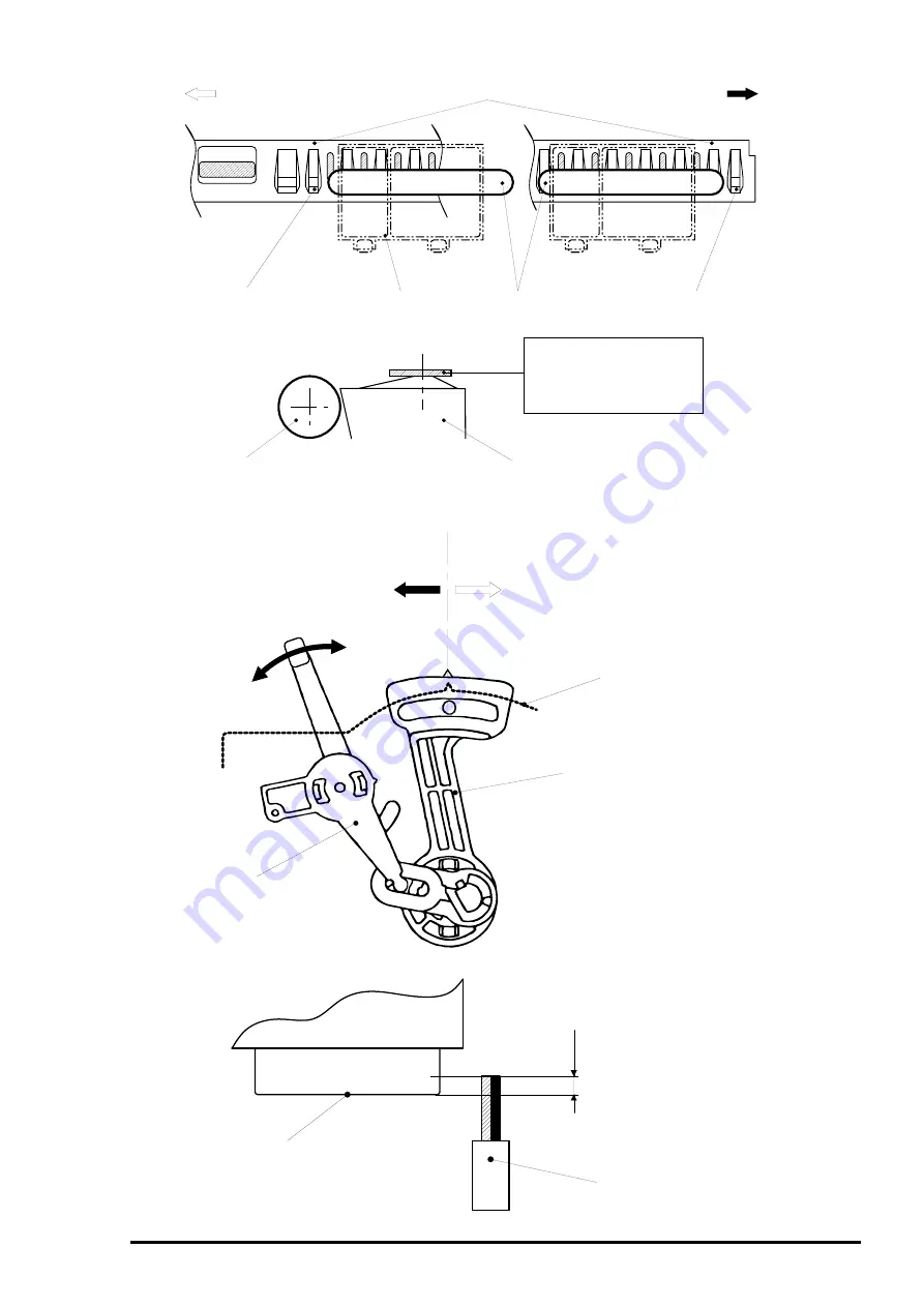
Front Paper Guide;B
Lib;Avoid 2 libs from left edge
Lib; Avoid 2 libs from right edge
Carriage
Thickness Gage
PF Roller Assembly
Front Paper Guide;B
Put the thickness gage flat
on the flat side of lib.
Also, match the center of
the thickness gage and
flat side of the lib.
Figure 4-1. Setting of the Gage at Parallel Adjustment
Frame
PG Lever
Parallelism Adjustment Bush
Standard Position Mark
Front
(Gap will be widened)
Rear
(Gap will be narrowed)
(+)
(0)
Figure 4-2. Parallel Adjustment
Print Head Side
Cleaner Head
Overlap amount
= More than 0.5mm
Figure 4-3. Overlap of Head Surface and Cleaner Brade
Summary of Contents for Stylus Color 400
Page 5: ...REVISION SHEET Revision Issued Data Contents Rev A February18 1997 First issue ...
Page 126: ...Chapter 6 Maintenance Rev A 6 5 No 1 No 2 10mm 2mm 2mm No 3 No 11 GEAR 34 ...
Page 138: ...EPSON Stylus Color400 Service Manual Rev A A 9 Figure A 3 C206 PSB Board Component Layout ...
Page 139: ...Appendix Rev A A 10 Figure A 4 C206 PSE Board Component Layout ...
Page 140: ...EPSON Stylus Color400 Service Manual Rev A A 11 Figure A 5 C206 PNL Component Layout ...
Page 141: ...Appendix Rev A A 12 A 5 Exploded Diagrams Figure A 6 Stylus Color 400 Exploded Diagram 1 ...
Page 143: ...Appendix Rev A A 14 Figure A 8 Stylus Color 400 Exploded Diagram 3 ...
Page 145: ...EPSON SEIKO EPSON CORPORATION ...


