background image

EPSON Stylus Color 900 (Revision C)

Color ink jet printer 

SEIJ98006

®


Summary of Contents for Stylus Color 900

Page 1: ...EPSONStylusColor900 RevisionC Color ink jet printer SEIJ98006 ...

Page 2: ...e contents of this manual However should any errors be detected SEIKO EPSON would greatly appreciate being informed of them The above not withstanding SEIKO EPSON CORPORATION can assume no responsibility for any errors in this manual or the consequences thereof EPSON is a registered trademark of SEIKO EPSON CORPORATION General Notice Other product names used herein are for identification purpose o...

Page 3: ...NOT CONNECT THE UNIT TO A POWER SOURCE UNTIL INSTRUCTED TO DO SO WHEN THE POWER SUPPLY CABLE MUST BE CONNECTED USE EXTREME CAUTION IN WORKING ON POWER SUPPLY AND OTHER ELECTRONIC COMPONENTS WARNING 1 REPAIRS ON EPSON PRODUCT SHOULD BE PERFORMED ONLY BY AN EPSON CERTIFIED REPAIR TECHNICIAN 2 MAKE CERTAIN THAT THE SOURCE VOLTAGES IS THE SAME AS THE RATED VOLTAGE LISTED ON THE SERIAL NUMBER RATING PL...

Page 4: ...bes the theory of electrical and mechanical operations of the product CHAPTER 3 TROUBLESHOOTING Provides the step by step procedures for troubleshooting CHAPTER 4 DISASSEMBLY AND ASSEMBLY Describes the step by step procedures for disassembling and assembling the product CHAPTER 5 ADJUSTMENTS Provides Epson approved methods for adjustment CHAPTER 6 MAINTENANCE Provides preventive maintenance proced...

Page 5: ...igure titles have been corrected Figure 4 14 Figure title and the contents of the figure have been corrected Chapter 5 Pages from 140 through 145 Head Angular Adjustment procedure has been changed due to overall review of the section C March 4 1999 The whole book is revised The actual change is made on the following points Chapter 4 Page 115 Figure 4 18 and step 3 Chapter 5 Page 135 to 141and Page...

Page 6: ...Mac Serial Interface 28 USB Interface 29 Printer Language and Emulation 29 Prevention Hosts from Data Transfer time out 29 Auto Interface Selection 29 IEEE 1284 4 Protocol 30 Control Panel Operation 31 Indicators LEDs 31 Panel Functions 32 Printer Setting Mode 32 Special Setting Mode 34 Printer Condition and Panel Status 35 Error Status 36 Ink Out 36 Paper Out 36 Paper Jam 36 No Ink Cartridge 36 M...

Page 7: ...Fan Removal 109 Shield Plate on the C265 Main Board Removal 110 C265 PSB PSE Board Removal 111 Printer Mechanism Disassembly 112 Printhead Removal 112 CR Motor Removal 114 PF Motor Removal 115 Pump ASF Motor and Solenoid Removal 116 ASF Unit Removal 116 ASF Sensor Removal 121 CRHP Sensor Removal 122 PE Sensor Removal 122 Encoder Belt Sensor Removal 123 Carriage Unit Removal 124 Pump Unit Removal 1...

Page 8: ...Component Layout 180 Parts List 184 Exploded Diagrams 187 Circuit Diagrams 195 ...

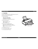
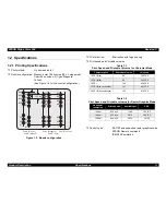
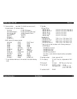
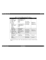
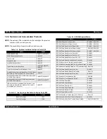
Page 9: ... PRODUCTDESCRIPTION ...

Page 10: ...ional and New Microweave Imprevement in color rendering using variable dot Built in auto sheet feeder Holds 100 cut sheets 64 g m2 Holds 10 envelopes Holds 30 transparency fIlms Built in 3 I F and 1 optional I F card slot Mac serial I F up to approximately 1 8 Mbps Bi directional parallel I F lEEE 1284 level 1 device USB Optional Type B level 2 I F card slot 4 scaleable fonts 5 LQ fonts 13 charact...

Page 11: ... IBM X24E emulation 3 6 0 d p i 1 8 0 d p i 1 9 6 9 6 9 5 9 4 9 3 2 3 9 5 9 4 9 3 9 6 9 5 9 4 9 3 1 2 3 1 2 3 9 6 9 5 9 4 9 3 1 2 3 R o w A B l a c k 1 R o w B B l a c k 2 R o w C M a g e n t a R o w D C y a n R o w E Y e l l o w Table 1 1 Print Speed and Printable Columns for Character Mode Character pitch Printable columns LQ speed 10 CPI Pica 80 285 CPS 12 CPI Elite 96 342 CPS 15 CPI 120 428 CP...

Page 12: ...d in the Default setting mode Typeface Bit map LQ font EPSON Roman 10 CPI 12 CPI 15CPI Proportional EPSON Sans Serif 10 CPI 12 CPI 15CPI Proportional EPSON Courier 10 CPI 12 CPI 15CPI EPSON Prestige 10 CPI 12 CPI 15CPI EPSON Script 10 CPI 12 CPI 15CPI Scaleable font EPSON Roman 10 5 pt 8 pt 32 pt every 2 pt EPSON Sans Serif 10 5 pt 8 pt 32 pt every 2 pt EPSON Roman T 10 5 pt 8 pt 32 pt every 2 pt ...

Page 13: ...n EPSON Sans Serif EPSON Roman T EPSON Sans Serif H NLSP version Italic table PC 850 Multilingual PC 861 Icelandic Abicomp lSOLatin1 ISO 8859 15 PC 437 US Standard Europe PC 860 Portuguese PC 865 Nordic BRASCIl Roman8 PC 858 PC437Greek PC 853 Turkish PC 857 Turkish PC 869 Greek Code MJK CSFR lSO Latin 1T Turkish PC7 74 1SO 8859 2 lSO Latin 2 PC 866 UKR PC 852 East Europe PC 855 Cyrillic PC 866 Rus...

Page 14: ...C83623 Items Codes Black Ink Cartridge T003 Color Ink Cartridge T005 Items Codes EPSON 360 dpi Ink Jet Paper A4 S041059 S041025 EPSON 360 dpi Ink Jet Paper Letter S041060 S041028 EPSON Photo Quality Ink Jet Paper A4 S041061 S041026 EPSON Photo Quality Ink Jet Paper Letter S041062 S041029 EPSON Photo Quality Ink Jet Paper Legal S041067 S041048 EPSON Photo Quality Ink Jet Card A6 S041054 EPSON Photo...

Page 15: ...idth 216 mm 8 5 x Length 279 mm 11 0 A6 Width 105 mm 4 1 x Length 148 mm 5 8 Thickness 0 075 mm 0 003 0 085 mm 0 0033 Paper Types EPSON special media NOTE Print on transparency at normal temperatures only 1 2 3 3 Envelope Thickness 0 08 mm 0 003 0 11 mm 0 004 Size No 10 Width 241 mm 9 1 2 x Length 104 8 mm 4 1 8 DL Width 220 mm 8 7 x Length 110 mm 4 3 C6 Width 162 mm 6 4 x Length 114 mm 4 5 5 x 8 ...

Page 16: ...mm 8 3 x Length 297 mm 11 7 Letter Width 216 mm 8 5 x Length 279 mm 11 0 4 x 6 Width 102 mm 4 x Length 152 mm 6 Panoramic Width 210 mm 8 3 x Length 594 mm 23 4 Paper Types EPSON special media 1 2 3 7 Photo Stickers Size A6 with 4 or 16 frames Width 105 mm 4 1 x Length 148 mm 5 8 Paper Types EPSON special media ...

Page 17: ...eed area P r i n t a b l e a r e a B M P L T M R M P W L M L M L e f t M a r g i n e R M R i g h t M a r g i n e T M T o p M a r g i n e B M B o t t o m M a r g i n e P W P a p e r W i d t h P L P a p e r L e n g t h Paper Size Left Margin Minimum Right Margin Minimum Top Margin Minimum Bottom Margin Minimum A4 3 mm 0 12 3 mm 0 12 3 mm 0 12 14 mm 0 54 3 mm 0 12 3 A5 3 mm 0 12 3 mm 0 12 3 mm 0 12 1...

Page 18: ...le 1 8 Minimum Margin for Envelopes Figure 1 4 Printable Area for Envelopes Paper Size Left Margin Minimum Right Margin Minimum Top Margin Minimum Bottom Margin Minimum 10 3 mm 0 12 28 mm 1 10 3 mm 0 12 14 mm 0 54 DL 3 mm 0 12 7 mm 0 28 3 mm 0 12 14 mm 0 54 C6 3 mm 0 12 3 mm 0 12 3 mm 0 12 14 mm 0 54 5 x 8 3 mm 0 12 7 mm 0 28 3 mm 0 12 14 mm 0 54 R M L M P r i n t a b l e A r e a B M T M ...

Page 19: ... Letter Pattern at 360 dpi Ink life 2 years from indicated production date Storage temperature Storage 20 C 40 C within a month at 40 C Packing storage 30 C 40 C within a month at 40 C Transit 30 C 60 C within 120 hours at 60 C and within a month at 40 C Dimensions 28 9 mm W x 67 4 mm D x 41 8 mm H Figure 1 5 Black Ink Cartridge Appearance 2 8 9 m m 6 5 9 m m R i b a r e a 4 1 8 m m 2 7 4 m m R i ...

Page 20: ...th at 40 C Packing storage 30 C 40 C within a month at 40 C Transit 30 C 60 C within 120 hours at 60 C and within a month at 40 C Dimensions 54 0 mm W x 67 4 mm D x 41 8 mm H NOTES 1 Do not refill the cartridge It is a consumable item 2 Do not used the ink cartridge whose ink life has expired 3 Ink will be frozen below 4 C To use ink that is frozen let it defrost for at least 3 hours at room tempe...

Page 21: ...ut frequency range 49 5 60 5Hz Rated current 0 2 A Maximum 0 3A Power consumption Approx 18W ISO IEC 10561 Letter pattern Energy Star compliant Insulation Resistance 10M ohms min between AC line and chassis DC500V Dielectric strength AC1500 V rms 1 minute between AC line and chassis 1 2 7 Environmental Condition Temperature Operating 10 to 35 C See Figure 1 7 Non operating 20 to 60 C 2 1 month at ...

Page 22: ...art B class B CSA C108 8 class B 220 240V version Safety standard EN 60950 VDE EMI EN55022 CISPR Pub 22 class B AS NZS 3548 class B 1 2 10 Acoustic Noise Level Approximately 47 dB A According to ISO 7779 1 2 11 CE Marking 220 240 V version Low Voltage Directive 73 23 EEC EN60950 EMC Directive 89 336 EEC EN55022 Class B EN61000 3 2 EN61000 3 3 EN50082 1 IEC801 2 IEC801 3 IEC801 4 1 2 12 Physical Sp...

Page 23: ...hese signals return to an inactive state The BUSY signal is HIGH During data entry see Data transmission timing When the input data buffer is full While INIT signal is at LOW level or during hardware initialization During a printer error condition See ERROR signal When the parallel interface is not selected The ERROR signal is LOW when one of the following error has occurred Printer hardware error...

Page 24: ...e when the printer is turned on The receiver provides an impedance equivalent to 7 5 K Ω to ground See Table 1 12 which shows the connector pin assignment and signals for the forward channel of the parallel interface Table 1 9 Data Transmission Timing Parameter Minimum Maximum tsetup 500ns thold 500ns tstb 500ns tready 0 tbusy 500ns tt out 120ns tt in 200ns treply 0 tack 500ns 10us tnbusy 0 tnext ...

Page 25: ...DATA4 24 7 DATA5 25 8 DATA6 26 9 DATA7 27 10 ACKNLG 28 O This signal is a negative pulse indicating that the printer can again accept data 11 BUSY 29 O A high signal indicates that the printer cannot receive data 12 PE 28 O A high signal indicates paper out error 13 SLCT 28 O Always at high level when the printer is powered on 14 AFXT 30 I Not used 31 INIT 30 I The falling edge of a negative pulse...

Page 26: ...s are 00H or 04H as follows 00H Request Nibble Mode Reverse Channel Transfer 04H Request device ID using Nibble Mode Rev Channel Transfer Device ID The printer sends following device ID string upon request When IEEE1284 4 is enabled 00H 60H MFG EPSON CMD ESCPL2 PRPXL BDC D4 MDL Stylus SP COLOR SP 900 CLS PRINTER DES EPSON SP Stylus SP COLOR SP 900 When IEEE1284 4 is disabled 00H 5DH MFG EPSON CMD ...

Page 27: ...sy Data Bit 3 7 29 O Printer busy signal and reverse channel transfer data bit 3 or 7 12 AckData Req DataBit 2 6 28 O Acknowledge data request signal and reverse channel transfer data bit 2 or 6 13 Xflag DataBit 1 5 28 O X flag signal and reverse channel transfer data bit 1 or 5 14 HostBusy 30 I Host busy signal 31 INIT 30 I Not used 32 DataAvail DataBit 0 4 29 O Data available signal and reverse ...

Page 28: ...Cable Apple System Peripheral 8 Cable Connector pin assignment and signal See Table 1 14 Table 1 14 Pin Assignment X ON X OFF DTR protocol See Table 1 15 Table 1 15 X On X Off and DTR Protocol Pin No Signal Name I O Description 1 SCLK O Synchronous clock signal 2 CTS I Clear To Send 3 TXD O Transmit Data 4 SG I Signal Ground 5 RXD I Receive Data 6 TXD O Balanced Transmit Data 7 DTR O Data Terminal...

Page 29: ...ter is in the busy state continuously when the input buffer is full 1 3 7 Auto Interface Selection The EPSON Stylus Color 900 has four types of interfaces USB parallel interface Mac serial interface and optional Type B interface Each interface can be selected manually in default setting mode or automatically Manual Selection One of four interfaces can be selected in default setting mode Automatic ...

Page 30: ...le that interface is not selected 1 3 7 1 IEEE 1284 4 Protocol The packet protocol described by IEEE1284 4 standard allows a device to carry on multiple exchanges or conversations which contain data and or control information with another device at the same time across a single point to point link The protocol is not however a device control language It does provide basic transport level flow cont...

Page 31: ... when the operate switch is ON and AC power is supplied 2 Paper out Lights during the paper out condition and blinks during the paper jam condition 3 Ink Out Black Lights during no Black ink condition and blinks during the Black ink low condition 4 Ink Out Color Lights during no Color ink condition and blinks during the Color ink low condition P o w e r L E D P o w e r B u t t o n L o a d E j e c ...

Page 32: ...s in the I C replacement position pressing this button returns the carriage to the capping position Load Eject for 2 seconds 1 Starts the I C replacement sequence 2 Move the carriage to the I C replacement position Cleaning for 2 seconds 1 Starts the printhead cleaning sequence Starts the I C replacement sequence when the printer is in one of the following conditions Ink Low Ink Out No Ink Cartrid...

Page 33: ...ry Table 1 20 Default Setting Menu Table 1 21 Default Setting Menu continued Underlined values are the defaults for the EEPROM reset Font Roman Sans Serif Courier Prestige Script Roman T Sans Serif H Draft Pitch 10 cpi 12 cpi 15 cpi 17 cpi 20 cpi Proportional Print direction Auto Bi D Uni D Loading Position 3 mm 8 5 mm Others I F mode Auto Parallel Serial USB Optional Auto I F wait mode 10 seconds...

Page 34: ...ct button 6 Press the Cleaning button 7 Repeat the steps from 3 to 6 until all test patterns are properly aligned 8 Turn the printer off 1 4 2 2 Special Setting Mode While turning the printer on pressing the both Load Eject and Cleaning buttons generates the Special setting mode While the Paper Out LED is blinking activate each function by pressing the specified button s in the method described in...

Page 35: ...le 1 23 Printer Condition and Panel Status Printer Status Indicators Priority Power Ink Out Black Ink Out CMY Paper Out Power on condition On 9 Ink Sequence mode Blink 6 I C replacement mode Blink 5 Data processing Blink 8 Paper Out On 4 Paper Jam Off Off Blink 3 No I C Ink Out Black On 7 Ink level low Black Blink 7 No I C Ink Out CMY On 7 Ink level low CMY Blink 7 Enters the EEPROM and Timer IC R...

Page 36: ... out it should never be used again Reinstalling the used cartridge not fully filled with ink upsets the ink level detection and may cause a serious problem in the printhead as a result 1 5 2 Paper Out When the printer fails to load a sheet it goes into the Paper Out error condition 1 5 3 Paper Jam When the printer fails to eject a sheet it goes into the Paper Jam error condition 1 5 4 No Ink Cartr...

Page 37: ...s the input data buffer c Clears the print buffer d Sets the default values Operator initialization This printer is initialized when it is turned on again within 10 seconds after last power off or recognizes the INIT signal negative pulse of the parallel interface When printer is initialized it performs the following a Caps the printhead b Ejects a paper c Clears the input data buffer d Clears the...

Page 38: ...deceleration areas by reading the slits on the linear scale to improve the throughput This improvement in throughput mostly depends on the Pump ASF switching mechanism In other printers the gear trains are switched when the trigger lever hits the mechanism along with the carriage s movement In Stylus Color 900 however the exclusive solenoid is directly attached to the mechanism instead With the so...

Page 39: ...aces but the USB I F and sensors while the latter controls the printhead motors encoder and USB I F The combined IC IC8 which has a normal timer IC and EERPOM in one chip also features the printer Since the EEPROM counts ink consumption at the valuable printing 1 its size has increased to 2 K bit 1 The valuable dot system or many valued dot system enables the printer to freely fire three different...

Page 40: ... N 1 0 C N 5 C N 6 C N 1 5 C N 1 3 T h e r m i s t o r d e t e c t s t e m p e r a t u r e o f t h e h e a t s i n k C h a r g i n g D i s c h a r g i n g d r i v e r f o r d r i v i n g t h e b l a c k n o z z l e s Q 5 u p p e r Q 6 l o w e r C h a r g i n g D i s c h a r g i n g d r i v e r f o r d r i v i n g t h e c o l o r n o z z l e s Q 3 u p p e r Q 4 l o w e r H e a t S i n k T h e r m i...

Page 41: ...pecially the heat sink to which the Q1 is attached can not be insulated due to the circuit s formation Therefore to avoid an electrical shock be careful not to touch the heat sink and other metallic parts simultaneously while troubleshooting Figure 1 12 C265 PSB PSE Board W A R N I N G Never touch the heat sink radiation plate on the Q1 with your bare hands as it is not insulated Otherwise you wil...

Page 42: ... W 2 S W 1 S W 0 C N 1 1 1 2 M C M C C R H P E A S F R E D W H T B L K M C C a r r i a g e h o m e p o s i t i o n C R H P s e n s o r C a r r i a g e C R M o t o r P u m p A S F M o t o r P a p e r F e e d P F M o t o r C o n n e c t o r f r o m t h e C N 1 1 o n t h e C 2 6 5 M a i n B o a r d C o n n e c t o r f r o m t h e C N 1 2 o n t h e C 2 6 5 M a i n B o a r d S o l e n o i d S w i t c h...

Page 43: ... OPERATINGPRINCIPLES ...

Page 44: ... 96 nozzles x 2 and 96 nozzles for each color This printhead enables the printer to print 3 lines by one pass at 10 cpi printing Also new ASF pump switching mechanism offers higher throughput with quick feeding motion at continuous printing by combining the trigger solenoid and independent pump ASF motor Production of PTS signal using the encoder belt also enables the printer to improve printing a...

Page 45: ...C d e t e c t i o n l e v e r C R u n i t C o l o r I C d e t e c t i o n l e v e r U n i t e d p r i n t h e a d f o r b l a c k a n d c o l o r T i m i n g b e l t C a p V a l v e f o r c a p p i n g P u m p C R H P s e n s o r C R g u i d e s h a f t P F r o l l e r p o w d e r y c o a t e d r o l l e r E n c o d e r b e l t A S F s e n s o r f o r p h a s e d e t e c t i o n A S F c a m A S F ...

Page 46: ... mode respectively Table 2 2 CRHP Sensor Specifications Table 2 3 CRHP Sensor Switch Mode If this sensor is defective or does not work it does not detect the carriage while the carriage is in the home position seek mode In this case the printer cuts off electricity to the CR motor and shows a fatal error Like the Stylus Pro5000 the Stylus color 900 also uses a linear encoder to obtain secure carri...

Page 47: ... jam error by bringing up the LEDs of the corresponding combination The printer is equipped with 2 actuators used to detect the ink cartridges in the carriage unit driven by the CR motor The printer however is designed to operate the actuators only when both black and color ink cartridges are installed See Table 2 5 and Table 2 6 for the ink cartridge sensor specifications and ink cartridge sensor...

Page 48: ...ial data consists of 96 data since each row is composed of 96 nozzles When these data is all transferred a Latch signal is output from the ASIC to the nozzle selector after specified period of time 5 When the Latch signal is sent a PZT signal is applied to the base side of the transistor via the latch circuit in the nozzle selector 6 Head drive pulse constantly output from the driver is then appli...

Page 49: ...cifications The ASF rotates the semicircular roller once in reverse before transporting paper into the printer Along with this motion the cam in the semicircular roller pushes up the return lever The return lever then bounces up with tension spring force As the result some paper which was fallen off the hopper during the previous feeding motion is all aligned and set back in the hopper This so cal...

Page 50: ... torque from the pump ASF motor is transmitted to the pump unit depending on the pump ASF mechanism condition The rotational directions and corresponding functions are as shown in Table 2 10 Table 2 10 ASF Pump Motor Functions S e m i c i r c u l a r r o l l e r C a m P i n c h r o l l e r H o p p e r R e t u r n l e v e r S e p a r a t i o n p a d R e a d y s t a t u s A c t i v e S t a t u s 1 2...

Page 51: ...mechanism is used to check the following 1 During paper loading checks if the leading edge of the paper from the ASF is correctly transported 2 Checks if the paper loaded meets the specifications 3 Checks if the paper is properly ejected after printing is over 4 Checks if paper is jamming See Table 2 12 and Table 2 13 for the PE sensor specifications and the PE sensor switch mode respectively Tabl...

Page 52: ...ndition the gear 3 in the planetary gear set and the pump transmission gear are in mesh 2 The pump ASF motor rotates in the normal direction CW 3 The whole planetary gear set tries to move up but the solenoid suppresses it 4 The solenoid comes on allowing the whole planetary gear set to move up At this point the gear 3 does not rotate but the motor pinion gear and gear 2 rotate in mesh 5 The gears...

Page 53: ...etary gear set tries to move down but the solenoid prevents it 10 The solenoid comes on allowing the whole planetary gear set to move down At this point the gear 3 does not rotate but the motor pinion gear and the gear 2 rotate in mesh 11 The gears 3 and 4 come in mesh and the connection to the pump gear train is fixed when a corner of the solenoid is aligned with the notch in the planetary gear s...

Page 54: ...ocess of torque transmission from the pump ASF motor to each mechanism Figure 2 8 Pump Carriage Lock Head Cleaner Mechanism C l u t c h S p a c e r C o m p r e s s i o n s p r i n g C l e a n e r h e a d F r a m e U n l o c k e d L o c k e d O n t h e s a m e s h a f t I n t h e p u m p g e a r t r a i n c o n d i t i o n P u m p i n t e r m i t t e n t g e a r P u m p t r a n s m i s s i o n g e ...

Page 55: ...ive is transmitted to the pressure roller right all parts used to drive the pump begin to act The Stylus Color 900 has the right and left pressure rollers However since the black and color heads are included in one unit the absorption tube is split in the middle so the 2 pumps can absorb ink in the printhead See Figure 2 9 which explains the ink absorption process 5 The cleaner head is located bet...

Page 56: ...r and also prevents leakage of higher harmonics generated in the printer After noise is removed the AC voltage goes through the full wave rectification circuit The minus component of the alternate wave is eliminated as the result Then the voltage is smoothed by the electrolysis condenser C11 for stabilized DC voltage and the current is applied to the primary side of the transformer T1 The current ...

Page 57: ...sms to detect abnormal rise in the voltage level caused by a defect in the circuit If the output voltage rises to 48 V the signal is input to a port of one of the 2 channels in the photocoupler PC1 to completely cut off the Q1 operation Once this circuit is active a normal flow does not recover unless the printer is turned off and back on 5 VDC production circuit L4960 IC51 produces 5 VDC out of 4...

Page 58: ... r r e n t p r o t e c t i o n H i g h e r h a r m o n i c s a b s o r p t i o n S m o o t h i n g F u l l w a v e r e c t i f i c a t i o n I n r u s h c u r r e n t t e m p e r a t u r e c o n v e r s i o n S t a r t i n g r e s i s t o r H i g h e r h a r m o n i c s a b s o r p t i o n S m o o t h i n g 5 V l i n e o v e r v o l t a g e p r o t e c t i o n S m o o t h i n g 4 2 V l i n e c o n...

Page 59: ... 1 2 8 I C 1 6 L B 1 8 4 7 I C 1 2 Q 9 Q 7 C N 1 3 F A N C N 1 6 A S F S o l e n o i d C N 8 H e a d 1 C N 9 H e a d 2 C N 1 2 A S F m o t o r C N 1 0 P F m o t o r C N 1 1 C R m o t o r S N 7 5 L B C I C 1 0 7 4 L V 1 6 1 2 8 4 I C 9 P R O M I C 4 D R A M I C 5 M R A M I C 6 E 0 5 B 6 0 I C 3 E 0 5 B 5 9 I C 2 H D 6 4 F 2 3 5 7 I C 1 C N 1 C e n t r o n i c s C N 3 M a c S e r i a l C N 2 T y p e...

Page 60: ...ry This IC also serves to produce reset signals connecting to each major IC such as CPU ASIC1 ASIC 2 and motor drive ICs The head driver ICs CXA2128 x 2 IC15 and IC16 individually produce a reset signal when detecting abnormal voltage so the printhead can stop in the proper sequence Component Functions Motor driver IC LB1847 IC11 12 A3957 IC13 14 The LB1847 IC11 and IC12 is used to drive PF motor ...

Page 61: ...ence On the other hand the timer control is done by counting the operation of the oscillator circuit and the printer s power off time can be confirmed based on the timer at the next power on operation Also this count data is used to manage the timer for the operation such as periodical flashing during power on time as well as power off time While the printer is on the printer supplies 5 V input to...

Page 62: ...ion circuit which is included in the nozzle selector inside the printhead The CPU s analog ports used for temperature detection and their functions are as follows Figure 2 13 Sensor Circuit Block Diagram Abnormal Temperature Detection Circuit A N O D E 5 C N 8 C N 9 T H M N o z z l e S e l e c t o r 4 H D 6 4 F 2 3 5 7 I C 1 T h e r m i s t o r o n t h e h e a t s i n k o n t h e m a i n b o a r d...

Page 63: ...formation the printer manages subtle change in the voltage level of the head drive trapezoidal waveform and also can eject the correct amount of ink as it is aimed at any temperature AN4 ANO Pins 1 2 9 10 4 The nozzle selector IC is attached inside the printhead It determines which nozzle is used to fire ink according to serial data sent from the ASIC IC2 A temperature detection circuit included i...

Page 64: ...the cartridge considering the following possible reasons 1 The currently installed ink cartridge is far beyond its useful life 6 months Ink in this condition does not eject properly and results in a false firing When a new cartridge is installed the problem is solved 2 The cartridge installed has been repeatedly removed and then installed again several times With this mis handling of the cartridge...

Page 65: ... part Figure 2 14 Sensor Circuit Block Diagram Mechanism Status Detection Part C N 9 2 0 2 1 C O B C O C 5 C N 8 2 1 2 0 L S 1 L S 2 E 0 5 B 5 9 I C 2 1 0 9 1 1 0 C O B C O C 9 3 9 4 E N C B E N C A 5 E 0 5 B 6 0 I C 3 S W C 0 S W A 1 S W A 0 1 3 7 1 3 6 1 3 5 5 5 3 3 P S C C N 1 5 H P P E A S F 1 6 1 5 1 4 4 C N 5 P S C 4 5 ...

Page 66: ...The printing column position is also confirmed based on the signals from the sensor Detection process The carriage is detected when the flag interrupts the light beam in the photo sensor which is located on the right end of the printer mechanism PE Paper End sensor The PE sensor detects the following conditions Whether or not paper is set at power on Whether or not paper is properly fed from the A...

Page 67: ... 9 1 7 1 1 7 2 L B 1 8 4 7 I C 1 2 1 5 1 7 3 1 7 4 1 7 5 N C M 6 2 3 8 3 I C 1 7 1 0 C R I A 0 C R I A 1 C R I A 2 C R I A 3 C R I B 0 C R I B 1 C R I B 2 C R I B 3 C R P H A A C R P H A B C R E N B A C R E N B B C R C T L 0 C R C T L 1 C R C T L 2 C R C T L R C R C T L S P h a s e A s e t t i n g c u r r e n t s i g n a l 1 6 p a t t e r n s P h a s e B s e t t i n g c u r r e n t s i g n a l 1 6...

Page 68: ...rdware and is equipped with the necessary number of input ports 8 ports for current setting signals Among these input ports 4 ports are allocated to each phase A and B Therefore 16 types of current setting data can be constantly sent to the driver IC The LB1847 controls the micro stepping system by exciting the corresponding phase based on the combinations of the setting signals sent from the ASIC...

Page 69: ... 7 2 1 3 1 4 0 1 3 9 1 3 8 1 3 7 1 3 3 1 3 4 1 3 5 1 3 6 1 4 2 1 2 8 1 4 1 1 2 9 1 2 4 1 2 7 L B 1 8 4 7 I C 1 1 1 2 5 1 2 6 1 2 3 N C M 6 2 3 8 3 I C 1 7 4 2 P F I A 0 P F I A 1 P F I A 2 P F I A 3 P F I B 0 P F I B 1 P F I B 2 P F I B 3 P F P H A A P F P H A B P F E N B A P F E N B B P F C T L 0 P F C T L 1 P F C T L 2 P F C T L R P F C T L S P h a s e A s e t t i n g c u r r e n t s i g n a l 1...

Page 70: ...ardware and is equipped with the necessary number of input ports 8 ports for current setting signals Among 8 input ports 4 are allocated to each phase A and B Therefore 16 types of current setting data can be constantly sent to the driver IC The LB1847 controls the micro stepping system by exciting the corresponding phase based on the combinations of the setting signals sent from the ASIC Table 2 ...

Page 71: ...rcuit Block Diagram 4 2 4 2 4 2 4 2 C N 1 2 1 3 2 4 A 3 9 5 7 I C 1 3 1 5 2 2 A 3 9 5 7 I C 1 4 1 5 2 2 R E F M 6 2 3 8 3 I C 1 7 D A x y 4 2 0 1 3 1 1 8 1 0 2 0 1 3 1 1 8 1 0 E 0 5 B 5 9 I C 2 6 9 6 8 6 2 6 4 6 3 8 1 8 0 7 2 7 4 7 3 A S F I A 0 A S F I A 1 A S F I A 2 A S F I A 3 A S F P H A A A S F I B 0 A S F I B 1 A S F I B 2 A S F I B 3 A S F P H A B A S F A A S F A A S F B A S F B P h a s e ...

Page 72: ...rial data is independently transferred to each nozzle row to enable reduction in data latch time required to form one dot while nozzle selection is performed by ASIC which sends serial data directly to the nozzle selector on the printhead synchronizing with the clock signal A block diagram and the circuit diagram for the nozzle selector are not included in this manual The printhead driver circuit ...

Page 73: ... W C L K 2 H W F L R H W S D A T A H W S L C H W S L A T A 0 A 1 A 2 A 3 C L K 1 C L K 2 F L O O R D A T A D C L K E V C C 4 5 V C C 4 5 _ 2 N P N B F B P N P B C h a r g i n g d i s c h a r g i n g c i r c u i t f o r c o l o r n o z z l e s B l a c k n o z z l e r o w s C o l o r n o z z l e r o w s H e a d t e m p e r a t u r e d e t e c t i o n c i r c u i t A N d a t a t e m p e r a t u r e d...

Page 74: ... from the lower case Figure 2 19 shows the cooling fan driver circuit block diagram Table 2 19 shows how the signals output from the ASIC and corresponding fan conditions Figure 2 19 Cooling Fan Driver Circuit Block Diagram Table 2 19 Cooling Fan Control by the ASIC IC2 Figure 2 20 shows the main routine of the cooling fan drive Figure 2 20 Main Routine of the Cooling Fan Drive ASIC IC2 176 pin co...

Page 75: ...eed In the error condition however the printer can lower the head drive frequency to 7 2 K Hz by reducing CR speed to 100 cpi Note the printer actually performs printing at 1 3 duty 1 pass of a normal speed Error 2 The printer stops printing In this condition the temperature at the junction of the power transistor for trapezoidal waveform production and the trapezoid waveform production IC pre dri...

Page 76: ...rol circuit block diagram respectively Table 2 21 ASF Solenoid Specifications Table 2 22 shows the ASIC s IC2 conditions for driving the ASF solenoid Table 2 22 Conditions for Driving the ASF Solenoid Figure 2 21 ASF Solenoid Control Circuit Block Diagram No Items Specifications 1 Type Single phase DC solenoid 2 Drive voltage 42 VDC 5 3 Coil resistance 588 Ω 10 at 20 C 4 Induction 0 98 N 100 gf or...

Page 77: ... by the ASIC IC3 In the D RAM the ASIC controls various adjustment values total ink consumption and current ink usage condition for each color and the printer prints depending on these values When the printer is turned off the data and adjustment values accumulated and controlled in the D RAM are written back into the specific addresses in the EEPROM under the ASIC s control Information is transmi...

Page 78: ... TROUBLESHOOTING ...

Page 79: ...g sections show detailed information on each step in the flowchart Be sure to perform troubleshooting without neglecting the correct order specified in each section Y e s N o T r o u b l e s h o o t i n g w i t h L E D e r r o r i n d i c a t i o n s S e c t i o n 3 1 1 S e c t i o n 3 1 3 I s t h e p r i n t e r p o w e r o n I s o l a t i n g t h e f a u l t y p a r t o n t h e p o w e r s u p p...

Page 80: ...Error On No I C or Ink Out Color Error On Maintenance Error Blink Blink Blink Blink Fatal Error Blink On On Blink No Error Condition Possible Causes 1 Paper Out Error Refer to Section 3 1 1 1 1 Failure in paper feeding 2 Connector for the PE sensor is disconnected 3 The PE sensor actuator is acting improperly The sensor base is not fixed properly 4 The PE sensor is defective 5 ASF is damaged 2 Pap...

Page 81: ...rectly attached to the printhead surface side is disconnected Note the connector green 4 pin is irrelevant as it is for the encoder 5 The micro switch is defective 6 The value for the ink consumption counter in the EEPROM is destroyed 7 Ink cartridge replace command is generated because an abnormal temperature is detected 4 Maintenance Error Refer to Section 3 1 1 4 Usual waste ink over flow is re...

Page 82: ...If the sensor base is floating or installed insecurely instal it securely C L S h e e t N o n a d h e s i v e A r e a A d h e s i v e A r e a T h i s s i d e d o w n U s e a p o s t c a r d f o r t h e b a s e s h e e t S t a p l e r s C l o t h m o i s t e n e d w i t h a l c o h o l B o t t o m v i e w o f t h e p r i n t e r m e c h a n i s m C o n n e c t o r f o r t h e P E s e n s o r T e n ...

Page 83: ...er whose length is beyond the specifications is used 2 Is the encoder located at the back of the CR covered with dust Check if there is any dust or paper debris lodged between the parts of the encoder a transmission type photo sensor located at the back of the carriage 3 Is the encoder belt nearly dislocated from the encoder Referring to the illustration above check if the encoder belt is nearly d...

Page 84: ...l continuity since checking the signal directly from the encoder is impossible 1 Connection of the connector 1 2 Connection of the connector 2 3 Electrical continuity of the cable C a r r i a g e v i e w e d f r o m t h e b a c k H e a d s u r f a c e C o n n e c t o r 1 C h e c k f o r c o n t i n u i t y C o n n e c t o r 2 Step Check Points Actions 7 Is the ASF installed improperly Is any of th...

Page 85: ...black and color ink adds up points according to ink weight used to form one dot This counter is reset the value returns to zero when the I C replacement sequence is performed If the counter is reset for any other purposes the following adversities will occur 1 Enough ink is remaining in the cartridge but the printer shows the Ink low or Ink end condition and can not continue to print 2 Ink has run...

Page 86: ...arbled and the printer shows the Ink Out Ink End error constantly the printer sets the interface signal BUSY to High and stops communication with any other peripheral devices Therefore it is effective to replace the I C with a new one to forcibly overwrite the address with 00H 7 Is the abnormal temperature detection circuit working Since the Stylus Color 900 drives a large number of PZT with a hig...

Page 87: ...t accept any data from the PC The EEPROM initialization mode initializes the following items Accumulated power off time The value for the Timer IC is reset CL Timer The CL timer which is also called fire waiting timer secures the printer specific period of time so bubbles formed around the printhead during a cleaning vanish I F selection Selects Auto the factory default from 4 I F selection items ...

Page 88: ...per debris between the sensor parts 2 Has the encoder belt come off Referring to step 2 in Section 3 1 2 2 check that the encoder belt is set between the sensor parts Also check that the sensor is free from dust and paper debris M C M C C R H P E A S F R E D W H T B L K M C C o n n e c t o r 1 C o n n e c t o r 2 M e c h a n i s m F r a m e Step Check Point Actions 3 Has the ASF sensor come off Is...

Page 89: ...stance 588 Ω 10 P u m p A S F S w i t c h i n g M e c h a n i s m P u m p A S F M o t o r L e v e r F i x i n g t h e P l a n e t a r y G e a r I r o n C o r e i n t h e S o l e n o i d T e n s i o n S p r i n g S o l e n o i d Step Check Point Actions 9 Is the CRHP sensor defective Check for the correct voltages at 3 pin connector shown in the figure below Turn the printer on and check the voltag...

Page 90: ...he FFC does not transfer signals the printer does not operate despite the power supply board and the main board are properly connected 3 Is the connector disconnected from the CN15 on the main board The reason is the same as above The panel control FFCs are connected via 1 CN15 on the main board 2 Relay board 3 Control Panel 4 Has the fuse F1 on the power supply board blown Check if the line in th...

Page 91: ... the NPN contact transistor is good the findings should be as shown under the figure Note the NPN connection transistor is shown in the circuit diagram as described below Step 1 On Step 2 Off Step 3 Off Step 4 On S t e p 1 G D S S t e p 2 G D S S t e p 3 G D S t e p 4 G D S t e p 1 S t e p 2 N P N T r S t e p 3 S t e p 4 B C E B C E B C E B C E Step Check Point Action 11 Is the PNP connection tran...

Page 92: ...olve the print problem Table 3 29 Table 3 33 7 Ink End Error occurs after the printhead is replaced so the printhead can not be adjusted Table 3 34 Step Check Point Action 1 Is the fuse F6 open Place the probes of the tester on the both terminals of the chip fuse F6 on the C265 Main board Then check for electrical continuity F6 is located beside the Q7 which is in front of the cooling fan connecto...

Page 93: ...e board with a screw M C M C C R H P E A S F R E D W H T B L K M C P h a s e A P h a s e B P h a s e A a n d P h a s e B f r o m t h e P i n 1 m a r k 2 0 V 2 0 µ Step Check Point Action 1 Getting ready for inspecting waveforms The connector used to control the PF motor is indicated in the figure below Using the oscillo scope check for the waveform for each phase output from the indicated connecto...

Page 94: ...robe of the oscillo scope to the tapped hole in the bottom plate on the board with a screw Note the connector has no ground line since this printer drives the motor with the bipolar system M C M C C R H P E A S F R E D W H T B L K M C P h a s e A P h a s e B P h a s e A P h a s e B f r o m t h e P i n 1 m a r k Step Check Point Action 2 Check of the waveform and remedies While trying to drive the ...

Page 95: ...plied Then press the Load Eject button and check if the voltage drops to 0 VDC for an instant If it does it means the Q8 is working properly The Q8 is located between CN12 and CN16 Q 8 2 0 V 2 0 2 0 V 2 0 µ µ Step Check Point Action 3 Is the transistor Q9 defective Place the probe of the oscillo scope on the emittor side of the transistor Q9 on the C265 Main board then check that voltage is always...

Page 96: ... aslant as shown below disconnect the FFC once and connect them again then run a print check NOTE Before reinstalling the FFCs be sure to remove the frame in red in the figure secured to the lower case with two screws Otherwise proper continuity may not be guaranteed despite the FFCs look connected without slant F r a m e H e a t S i n k C h e c k t h a t t h e c o n n e c t o r s a r e n o t c o ...

Page 97: ...s p r e s s u r e L e f t t u b e s e m i t r a n s p a r e n t I n k a b s o r p t i o n R i g h t t u b e w h i t e C W C C W S e p a r a t o r F F C 2 F F C 1 Step Check Point Action 8 Is the head driver transistor defective If you see the C265 Main board from the heat sink side the following four power transistors can be found Q3 and Q4 Outputs the common voltage for the row A and B black nozz...

Page 98: ...tput correctly replace the corresponding power transistor T H H e a t S i n k Q 4 Q 3 Q 6 Q 5 D 2 0 8 2 B 1 3 8 2 D 2 0 8 2 B 1 3 8 2 B E T r f o r t h e b l a c k n o z z l e s T r f o r t h e c o l o r n o z z l e s 2 0 V 2 µ Step Action 1 Turn the printer power off 2 Replace the printhead 3 Turn the printer back on The printer is in No Ink Cartridge condition 4 Keep the Load eject button presse...

Page 99: ...five rows in total can be independently monitored Refer to Chapter 2 Section 2 3 2 6 Once the abnormal temperature detection circuit is active the printer stops printing and starts a forcible cleaning This operation cleans the clogged nozzles and the ink inside the printhead flow properly as a result At this point the printer sets the flag in the address for the abnormal temperature detection circ...

Page 100: ...s monitoring the temperatures before the printhead ID on the board is replaced with a new one then shows the error consequently On the other hand if you follow the proper steps Head replacement Turning on the printer proper I C replacement with a new one the program allows a data transfer once before printing so you can overwrite the printhead ID Nozzle Selector 1st digit of the Head ID The board ...

Page 101: ... DISASSEMBLYANDASSEMBLY ...

Page 102: ...rinter Wear protective goggles to protect your eyes from ink If ink gets in your eye flush the eye with fresh water and see a doctor immediately If ink comes into contact with your skin wash it off with soap and water If irritation occurs contact a physician A lithium battery is installed on the main board of this printer Be sure to observe the following instructions when serving the battery Keep ...

Page 103: ...un type équivalent recommandé par le fabricant Eliminer les piles déchargées selon les lois et les règles de sécurité en vigueur C A U T I O N Never remove the ink cartridge from the carriage unless the manual specifies to do so When transporting the printer after the ink cartridge has been installed be sure to pack the printer for transport without removing the ink cartridge Use only recommended ...

Page 104: ...i n B o a r d R e m o v a l S T A R T U p p e r C a s e C o n t r o l P a n e l R e m o v a l P r i n t e r M e c h a n i s m R e m o v a l P r i n t h e a d R e m o v a l P F M o t o r R e m o v a l P u m p A S F M o t o r S o l e n o i d R e m o v a l C R H P S e n s o r R e m o v a l P E S e n s o r R e m o v a l E n c o d e r B e l t R e m o v a l C a r r i a g e U n i t R e m o v a l P u m p ...

Page 105: ...quence 2 Head Actuator Voltage ID Input 3 Ink Charge Flag Reset 4 Head Angular Adjustment 5 Bi Directional Adjustment C265 Main board 1 Head Actuator Voltage ID Input 2 Bi Directional Adjustment CR shaft 1 Remove the Printhead and CR Unit 2 Remove the oil pad Refer to Chapter 6 3 Clean and lubricate the carriage guide shaft 4 Reinstall the printhead and the CR Unit 5 Perform the Parallelism adjust...

Page 106: ...s securing the control panel to the printer mechanism to release the control panel Then disconnect the FFC from the control panel and remove the control panel from the printer 7 Remove four screws securing the upper case When assembling note the only CBS Tight screw among four must be used at the rear right of the upper case 8 Lift up the front edge of the upper case then remove the whole case by ...

Page 107: ...Connector for PE sensor Connector for CR motor Connector for CRHP Carriage Home Position sensor Figure 4 5 Connector Location Cable Holder Relay Board Screws securing the Printer Mechanism Printhead FFCs Screws securing the Waste Ink Drain Pads Screw securing the Printer Mechanism When assembling be sure to connect the connectors properly as shown in Figure 4 5 C H E C K P O I N T M C M C C R H P ...

Page 108: ...curing the Type B interface cover to the printer and remove the rear case 4 Disconnect two connectors CN5 and CN6 from the C265 Main board and remove the C265 Main board unit C A U T I O N After replacing the Waste Ink Pads perform any necessary adjustments See Table 4 1 When installing the FFCs remove the frame secured by two screws before connecting the FFCs Otherwise the FFCs will not be connec...

Page 109: ...the relay board to the shield plate on the C265 Main board then remove the relay board 4 Remove three screws securing the cooling fan unit to the shield plate on the C265 main board then separate the cooling fan from the C265 Main board 5 Disconnect the connector CN13 white 2 pin from the C265 Main board and remove the cooling fan unit Figure 4 7 Relay Board and Cooling Fan Removal Screws securing...

Page 110: ...r CN15 on the C265 Main board 5 Remove two screws securing the shield plate top to the bottom frame and remove the shield plate top 6 Remove the Type B interface guide 7 Remove four screws securing the C265 Main board onto the bottom frame Two screws among the four are fixing the reinforcing plate for the Type B interface guide 8 Viewing the C265 Main board from the Centronics I F connector side r...

Page 111: ... PSB PSE board to the lower case then remove the C265 PSB PSE board unit Figure 4 10 Removing the Connectors 4 Remove two screws securing the shield plate on the C265 PSB PSE board and remove the shield plate Figure 4 11 Removing the Shield Plate 5 Remove four screws securing the C265 PSB PSE board to the bottom frame and remove the C265 PSB PSE board Figure 4 12 C265 PSB PSE Board Removal Screws ...

Page 112: ...ints black in the cartridge clamps from the carriage unit and remove the cartridge clamps 6 Remove the compression spring on the left side of the carriage unit 7 Releasing three hooks securing the cover protecting 2 ink cartridge sensors in the carriage unit remove the cover 8 Remove the FFC holder on the right edge of the carriage unit by pulling it upward C A U T I O N When removing the printhea...

Page 113: ... of the I C Detection Actuator 11 Disconnect the green connector for the ink cartridge sensor from the carriage unit 12 Lifting up the printhead unit disconnect 2 FFCs and the connector green 4 pin for the ink cartridge sensor Figure 4 16 Printhead Removal 2 Actuators C H E C K P O I N T When installing the printhead FFCs make sure the reinforcing plates on the FFC are installed correctly as descr...

Page 114: ...he carriage lock at the back of the printer mechanism then move the carriage unit away from the home position See Figure 4 13 3 Remove two screws securing the CR motor to the printer mechanism and remove the CR motor Figure 4 17 CR Motor Removal Screw securing the CR Motor C A U T I O N After removing replacing the CR Motor perform any necessary adjustments See Table 4 1 ...

Page 115: ...fore if the PF roller drive gear has been removed it must not be used again Neglecting this may cause a printer malfunction When installing a new PF roller drive gear be sure to push it intensively by its center area not forcing a push by its edge Figure 4 19 PF Roller Driver Gear Installation C A U T I O N PF motor pinion gear as well as the PF roller drive roller is a high precision gear Therefo...

Page 116: ... 20 Pump ASF Motor and Solenoid Removal 4 2 7 5 ASF Unit Removal 1 Remove the DE subassembly frame See Section 4 2 7 4 2 Inserting tweezers from the inner side release the joint for the ASF drive gear and the ASF drive shaft to remove the ASF drive gear 3 Remove two screws securing the ASF unit 4 Holding the paper hold lever up to the left remove the ASF unit Figure 4 21 ASF Removal Screw securing...

Page 117: ...al 5 Release the peg fixing the hopper assembly to the ASF frame by the top left Then separate the hopper assembly and the ASF frame Figure 4 25 Separating the Hopper Assembly from the ASF Frame B u s h i n g F i x i n g t h e S h a f t o n t h e L e f t L D R o l l e r S h a f t S h a f t s S i d e F a c e L D R o l l e r S h a f t R e l e a s e H o p p e r L e v e r R i g h t C H E C K P O I N T...

Page 118: ...se one hook securing the LD roller cover in the paper loading assembly and remove the LD roller cover Figure 4 26 LD Roller Cover Removal 9 Release four hooks securing the LD roller assembly to the frame in the paper loading assembly and remove the LD roller assembly Figure 4 27 LD Roller Assembly Removal P a p e r L o a d i n g A s s e m b l y L D R o l l e r C o v e r L D R o l l e r C o v e r C...

Page 119: ... e m b l y C o m p r e s s i o n S p r i n g 1 6 6 T o r s i o n S p r i n g R o d S p r i n g When installing the LD roller shaft with the both paper loading assemblies on it into the ASF frame shift the right paper loading assembly to the right edge of the ASF frame then fix it by aligning the groove in the back of the paper loading assembly with the rail ribs on the inner side of the ASF frame ...

Page 120: ...i n t h e b a c k o f t h e A S F F r a m e S t r a i g h t E n d o f t h e C o m p r e s s i o n S p r i n g 1 6 6 Be sure to fix both right and left pegs on the ASF frame securely into the sockets in the hopper assembly When installing the detection wheel onto the left end of the LD roller shaft align the protruding portion of the LD roller shaft with the concave portion of the detection wheel E...

Page 121: ... hook securing the detection wheel and push the detection wheel to remove Figure 4 33 Detection Wheel Removal 4 Disconnect the connector from the ASF sensor 5 Using tweezers release one of the hooks securing the ASF sensor and remove the ASF sensor Figure 4 34 ASF Sensor Removal B u s h i n g F i x i n g t h e S h a f t o n t h e L e f t L D R o l l e r S h a f t F i x i n g T a b D e t e c t i o ...

Page 122: ...e CRHP sensor remove the CRHP sensor Figure 4 35 CRHP Sensor Removal 4 2 7 8 PE Sensor Removal 1 Remove the printer mechanism See Section 4 2 2 2 Release the hook securing the PE sensor at the back of the printer mechanism and remove the PE sensor Figure 4 36 PE Sensor Removal CRHP Sensor Push the hooks H o o k s A t t a c h i n g t h e P a p e r E n d S e n s o r T o p F r a m e L o c a t i o n h...

Page 123: ...then remove the encoder belt when the encoder belt is released enough Figure 4 37 Encoder Belt Removal Fixing Lever Encoder Belt Linear Scale C A U T I O N When installing the encoder belt be sure to place it between the flags for the photo sensor attached to the back of the carriage unit Failure to do so will bring a fatal error at power on Figure 4 38 Positioning the Encoder Belt L i n e a r S c...

Page 124: ...usting lever with tension 6 Release the hook securing the paper thickness adjusting lever to the printer mechanism then push the paper thickness adjusting lever inward to remove it Figure 4 40 PG Adjust Lever Removal 7 Remove the E ring fixing the carriage guide shaft and the parallelism adjustment bushing right and then the washer and the spring washer to release the parallelism adjustment bushin...

Page 125: ... 2 7 11 Pump Unit Removal 1 Remove the printer mechanism See Section 4 2 2 2 Remove three screws securing the pump unit and remove the pump unit along with the frame Figure 4 42 Pump Unit Removal C A U T I O N After removing replacing the Carriage Unit Carraige Guide Shaft perform any necessary adjustments See Table 4 1 When removing the carriage guide shaft pay atttention to the oil pad as it wil...

Page 126: ...rame and the other on the right frame and remove the FFC holders Figure 4 43 Paper Eject Frame Removal 5 Remove two screws securing the paper eject frame and remove the paper eject frame 4 2 7 13 Paper Eject Roller Removal 1 Remove the paper eject frame See Section 4 2 7 12 2 Turning the bushings fixing the paper roller by the both ends upwards and remove the paper eject roller Figure 4 44 Paper E...

Page 127: ...sion C Disassembly and Assembly Disassembly Procedures 127 4 2 7 14 Platen Removal 1 Remove the paper eject roller See Section 4 2 7 13 2 Lift up the front edge of the platen and remove the plate Figure 4 45 Platen Removal Platen ...

Page 128: ...r 4 Pull all the paper guides upper out to the front side of the printer mechanism paper ejection side 5 Remove the tension spring stretching the encoder belt from the back of the printer mechanism Figure 4 48 Tension Spring Removal 6 Remove two screws securing the top frame and remove the top frame Screw Securing the Paper Support Lever Torsion Spring six springs in total Paper Guides Upper C A U...

Page 129: ...re 4 50 Top Frame Removal 2 8 among two bushings securing the PF roller by the both ends turn the left one on the 80th column side upward to release the PF roller then shift the whole shaft to the right and remove the PF roller The paper guide lower is remove together Figure 4 51 PF Roller Removal Top Frame Screws securing the Top Frame Screw securing the Top Frame at the back C A U T I O N Never ...

Page 130: ... ADJUSTMENT ...

Page 131: ... in the correct order Failure to do so may directly affect to print quality adversely In this printer the head angle adjustment can be done without removing the upper case However since the head fixing plated is installed with two screws observe the instruction in this manual to perform the adjustment properly The C language used in the service program only applies to the PCs which run DOS V There...

Page 132: ... CG and default value 3 Input a 22 digit ID in Head Actuator Voltage ID Input using the service program 4 Perform Bi Directional Adjustment using the service program No Actions taken Step Corresponding adjustment required 3 CR shaft replacement or cleaning 1 Referring to Chapter 6 Maintenance remove the oil pad from the carriage 2 Referring to Chapter 6 Maintenance perform the followings 1 Clean t...

Page 133: ...program 2 If the step 1 is not effective perform Ink Charge Flag Reset using the service program and then turn the printer off In 10 seconds turn the printer back on and Initial Ink Charge begins automatically 5 Waste Pad replacement 1 Replace the waste ink pad 2 Return the current counter values for the waste ink pads to zero by selecting Indication of the counter value of waste ink pad then Clea...

Page 134: ...e you are dealing with correctly The command required to write adjustment value for each adjustment includes a model unique parameter which is called R code The purpose of selecting the model name is to define the parameter which is specific to the model 6 The following screen appears Figure 5 2 Destination Selection Screen 7 From the option in screen Figure 5 2 select the destination which applie...

Page 135: ...a 1 Resets the Hardware 2 Returns to the idles state 3 Reads the model name For this reason the printer takes 25 30 seconds to read data Since the service program for the Stylus Color 900 shows the countdown to inform the service person of the period of time to wait until the whole process from the writing to the EEPROM to reading data is completed 10 Select Perform Boot this program 11 The main a...

Page 136: ...o Market Destination Check and press the Enter key 5 The following screen appears Figure 5 6 Market Destination Check Selection Screen 6 Press the Enter key again 7 The following screen appears The screen enables you to check the selection made in Section 5 2 1 Step 6 The following figure is a sample screen when the NLSP version for EDG is selected E S C Q u i t U p D o w n a r r o w s S e l e c t...

Page 137: ...t i n a t i o n E s c P r e v i o u s M a r k e t D e s t i n a t i o n i s W o r l d N L S P H e a d A c t u a t o r V o l t a g e I D I n p u t E s c P r e v i o u s U p D o w n a r r o w s S e l e c t E n t e r O K C h e c k p r e s e n t d a t a I n p u t d a t a T h e r e i s a p o s s i b i l i t y t h a t y o u e n c o u n t e r t h e i n k o u t e r r o r i f y o u i g n o r e t h e f o l ...

Page 138: ...A B or C New printhead The 22th digit is D or newer Due to the diversity of versions there are total of four combinations of ROM version and printhead ID For two combinations of them however the program prompts ROM replacement or converts head ID to be registered This is required to keep the print quality even among all combinations This complicated operation can be easily done by following the us...

Page 139: ...r a m p r o m p t s t o r e p l a c e t h e o l d R O M w i t h t h e r e v i s e d o n e T E E 0 1 D o r n e w e r a n d p r e s s t h e Y k e y a f t e r r e p l a c e m e n t H e a d I D i n p u t s c r e e n 1 I D i n p u t m e n u T h e i n p u t I D i s r e g i s t e r e d i n t h e E E P R O M w i t h o u t c o m p e n s a t i o n H e a d I D i n p u t s c r e e n 2 W h a t d o e s t h e 2 ...

Page 140: ...that the ID has been input in the EEPROM it is actually written into the EEPROM when the printer is turned off 11 Press ESC key twice The screen returns to the sub adjustment menu screen to continue to the next adjustment Figure 5 12 22 digit ID Input Sequence E n t e r t h e 2 2 d i g i t v o l t a g e I D N e w R O M H E A D A C T U A T O R V O L T A G E I D H E A D A C T U A T O R V O L T A G E...

Page 141: ...stment 2 The following screen appears Figure 5 13 Adjustment 2 Selection Screen 3 Select Head Angular Adjustment The following screen appears Figure 5 14 Head Angular Adjustment Initial Screen 4 Select Print the head angular adjustment pattern to check the current head angular condition 5 The following screen appears and the printer starts running Head Angular Adjustment Pattern Figure 5 15 Screen...

Page 142: ...omatically returned to the Head Angular Adjustment Initial screen Figure 5 14 where you are to select Head Angular Adjustment P a t t e r n 1 O K P a t t e r n P a t t e r n 2 P a t t e r n 3 P a t t e r n 4 P a t t e r n 5 W h i t e l i n e s a p p e a r s y m m e t r i c a l l y N G P a t t e r n P a t t e r n 1 P a t t e r n 2 P a t t e r n 3 P a t t e r n 4 P a t t e r n 5 W h i t e l i n e s ...

Page 143: ...to move the carriage the printer directly enters the carriage lock lever releasing operation without the rush current control which is done while magnetizing the motor As a result there is a possibility that the carriage collides because of the incompletely released lever and the error occurs Therefore please be aware that the program runs a cleaning that is originally supported by the hardware if...

Page 144: ... e r O K T h e p r i n t e r h a s b e e n l e f t a l o n e f o r 3 m i n u t e s T h e p u m p A S F m o t o r h a s n t b e e n p r o p e r l y m a g n e t i z e d a n d c a r r i a g e w i l l n o t m o v e P l e a s e p r e s s t h e E n t e r k e y N o w p e r f o r m C L 1 i n o r d e r t o r e c o v e r t h e m o t o r s m a g n e t i z e d s t a t e C L 1 t a k e s a b o u t 9 0 s e c o n...

Page 145: ... the Enter key in the screen Figure 5 25 19 The printer runs the Head Angular Adjustment Pattern The following screen appears Figure 5 27 Prompt to Move the Angular Adjustment Lever 20 Select Re Adjustment in the screen Figure 5 27 1 A f t e r y o u h a v e m o v e d t h e a n g u l a r a d j u s t m e n t l e v e r 2 p u s h t h e c o l o r I C f r o m f r o n t s i d e b y u s i n g f i n e d r ...

Page 146: ...own in Figure 5 28 29 In the screen Figure 5 28 press the Enter key 30 The printer prints with the angular lever set to the selected position The pattern however remains in the lower part of the mechanism frame and can not be seen The screen changes to the condition shown in Figure 5 27 NOTE Do not eject the sheet used in Step 30 by pressing the Eject button to check the pattern If you do so misma...

Page 147: ...riction on any action using the program and generating commands NOTE The Hardware Reset performed here which initializes the carriage location management is considered very important because there is a possibility that the print position changes slightly during the adjustment 34 The screen returns to Head Angular Adjustment Initial screen Figure 5 14 and the next adjustment can be selected E n t e...

Page 148: ...t Print the Bi D adjustment pattern in the screen 5 The following screen appears NOTE The following three items are adjusted with the Bi D Adjustment 1 Variable dot forms small middle dots 2 Variable dot forms normal dots 3 Normal dot only Figure 5 32 Screen after Print the Bi D adjustment pattern is Selected 6 Press the Enter key 7 The following screen appears and the printer runs the Bi D adjust...

Page 149: ...e most closely aligned pattern The centre value for the next adjustment pattern print will be replaced accordingly Figure 5 34 Bi D Adjustment Pattern Sample E S C P r e v i o u s E n t e r O K B i d p a t t e r n i s b e i n g p r i n t e d o u t n o w V a r i a b l e 1 D o t B i d D a t a 2 V a r i a b l e 1 D o t B i d D a t a 0 V a r i a b l e 1 D o t B i d D a t a 2 V a r i a b l e 2 D o t B ...

Page 150: ...ted press the Enter key The following screen appears Figure 5 37 Screen after the Adjustment Value has been Written 17 Press the ESC key to return to the Bi D Adjustment mode selection screen Figure 5 35 18 Select Variable 2 Dot If the center value for the Variable 2 Dot pattern has the completely aligned lines you can select Normal Dot instead 19 The following screen appears E S C P r e v i o u s...

Page 151: ...ing screen appears Figure 5 40 Adjustment Value Input Screen Normal Dot 25 As the Up Down Arrow key is pressed the value shown in blue in the figure increases decreases So you can select the desirable value NOTE Regardless of the value you have input the center value selected value in the next Bi D pattern sample will be 0 The value in the range from 34 to 34 can be input 26 When the desirable val...

Page 152: ... 1 Market Destination Check Press the ESC key twice and select Market Destination Check from the menu 2 Print A 4 Pattern Press the ESC key three times and select Print A4 Pattern from SERVICE ITEMS NOTE Bi Directional Adjustment is the last adjustment to be made on the program Never perform adjustments such as Head Angular Adjustment and Head Actuator Voltage ID Input after Bi Directional Adjustm...

Page 153: ...2 Main maintenance Menu Screen 4 Select Head Cleaning 5 The following screen appears Figure 5 43 Cleaning Screen 6 Press the Enter key 7 To run the cleaning again press the ESC key once to return to the main maintenance menu and select Head Cleaning E P S O N S t y l u s C O L O R 9 0 0 S E R V I C E P R O G R A M V e r s i o n 1 0 M a i n t e n a n c e E s c Q u i t U p D o w n a r r o w s S e l ...

Page 154: ... Initial Ink Charge in sequence E s c P r e v i o u s U p D o w n a r r o w s S e l e c t E n t e r O K D o y o u w a n t t o r e s e t t h e i n i t i a l i n k c h a r g e f l a g Y e s N o B e c a r e f u l o f i n k c o n s u m p t i o n N o t e t h a t 1 7 0 B k 3 1 0 Y M C o f n o n u s e d i n k c o n s u m e d b y o n e t i m e P e r f o r m t h i s o p e r a t i o n a f t e r i n s t a l ...

Page 155: ...the counters continue to Step 7 NOTE Before clearing the protection counters be sure to replace the waste ink pads with new ones Otherwise the user may encounter ink leakage 7 Disconnect the printer from the PC and replace the waste ink pads with new ones referring to Chapter 6 Maintenance 8 Referring to Section 5 2 1 perform the preliminary operation Then select Maintenance from the main adjustme...

Page 156: ...een 13 Press the ESC key twice to return to the initial protection counter screen Figure 5 46 14 Select Check Protection Counter to verify the right and left ink pad counter values are both 0 E s c P r e v i o u s U p D o w n a r r o w s S e l e c t E n t e r O K T h e w a s t e i n k p a d s m u s t b e r e p l a c e d b e f o r e c l e a r i n g t h e c o u n t e r A l r e a d y r e p l a c e d ...

Page 157: ...menu 3 The following screen appears Figure 5 50 Screen after Fan Check is Selected 4 As the screen Figure 5 50 appears the cooling fan starts rotating If the fan is rotating properly select Yes and the fan stops rotating 5 If No is selected because the fan does not rotate the following screen appears In this case refer to the Service Manual Chapter 3 Troubleshooting Fan does not rotate as the mess...

Page 158: ...stall dummy cartridges empty cartridges and close the both clamps 3 Set the PG lever blue to the rear PG wider 4 If the carriage is locked release the carriage lock from the back of the printer mechanism 5 Move the carriage to the center and place the thickness gauge Specifications 1 14 mm 5 cm in length over the right end of the Front Paper Guide s top surface Figure 5 53 Setting Position of the ...

Page 159: ...s set and make sure the thickness gauge does not move 14 Place the thickness gauge on the 80th column position and adjust the with the left parallelism adjustment bushing in the same manner as for the right parallelism adjustment bushing NOTE Make sure the PG lever blue is set properly depending on the operation as shown below During the adjustment Set to the front PG narrower When moving the carr...

Page 160: ...d so it does not move fasten the screw 23 Holding the left parallelism adjustment bushing with your hand so it does not move fasten the screw 24 Remove the thickness gauge 25 If the linear scale is dislocated set it through the photo sensor at the back of the carriage 26 Move the carriage to the right 27 Install the upper case ...

Page 161: ... MAINTENANCE ...

Page 162: ...as a lithium battery on it Observe the instructions below when handling the battery Do not short circuit the battery s electrodes Mount the battery with its polarity in the right direction or it may explode Do not expose the battery to flames or excessive heat C A U T I O N Unplug the power cable from the AC power inlet before cleaning the printer Never apply solvents such as thinner trichloroethy...

Page 163: ... e s N o C l e a n i n g M e t h o d C l e a n i n g u s i n g t h e c o n t r o l p a n e l P r e s s t h e C l e a n i n g B u t t o n P e r f o r m c l e a n i n g a c c o r d i n g t o t h e C L c o u n t e r R u n a s e l f t e s t C l e a n i n g u s i n g t h e I n i t i a l I n k C h a r g e R e s e t t h e i n i t i a l i n k c h a r g e f l a g i n t h e p r o g r a m T u r n t h e p r i...

Page 164: ...ste ink counter NOTE Unlike other printers the waste ink counter reset operation is not common to Timer IC nor I F selection reset Chapter 1 Section 1 4 2 Using the program Waste ink count reset Chapter 5 Section 5 2 8 C A U T I O N Be sure to replace the waste ink pads before or after clearing the Maintenance Request Error Otherwise your customer may encounter ink overflow The maximum counter val...

Page 165: ...it and the carriage unit before replacing the current oil pad with a new one and then supplying oil to the new pad Accordingly you need to perform any necessary head related adjustment Refer to Chapter 5 C A U T I O N When installing the carriage guide shaft after oiling the oil pad be sure to clean the shaft and perform the preliminary lubrication before installing the shaft as described below 1 ...

Page 166: ...g the Carriage Guide Shaft 4 Remove the Oil Pad a felt pad from the back of the carriage unit 5 Using the dry cloth completely wipe the inner surfaces of the 2 metallic bushings through which the carriage guide shaft is set Especially wipe well off black stains if any Also clean the portion where the pad was attached using the cloth Figure 6 3 Locations for Oil Pad and Bushings 6 Get a smallest di...

Page 167: ...2 12 Install the carriage guide shaft to the carriage unit then to the printer main body See Chapter 4 Section 4 2 7 10 13 Install the printhead See Chapter 4 Section 4 2 7 1 14 Perform Paper Gap Adjustment See Chapter 5 Section 5 2 10 15 Turn the printer on without the ink cartridges installed to cause the Ink Cartridge Out Error 16 Using the Load Eject button run the Ink Cartridge Replacement Se...

Page 168: ...t Amount Ref figure 1 Apply oil to the Oil Pad Before lubricating observe the CAUTION in Section 6 2 well 0 7 0 75 cc Figure 6 14 No Lubricating Point Amount 1 The shaft in the Frame Assembly DE Right G 26 φ1 x 10 mm 2 The teeth of the Gear 25 8 G 26 φ1mm x 1 3 of the circle 3 The shaft in the Frame Assembly DE Left G 26 φ1 x 10 mm 4 The teeth of the smaller gear in the Combination Gear 12 26 G 26...

Page 169: ...R NOTE Do not apply lubricant to the Shaft CR Support O 8 18 Shaft hole of the Combination Gear 29 6 29 6 G 26 φ1 x 5 mm 19 The areas where the Combination Gear 29 6 29 6 and Combination Gear 15 2 23 2 come in contact with the Mounting Plate Assembly Cap NOTE Do not apply lubricant to the shaft of the Combination Gear 15 2 23 2 which joins with the hole in the Pump Assembly G 26 φ1 x 5 mm G 2 6 F ...

Page 170: ...rication and Adhesion 170 G 26 S h a f t P u l l e y D r i v e n G 2 6 B a c k o f t h e C a r r i a g e G 2 6 B a c k o f t h e F r a m e G u i d e C R G 2 6 Figure 6 10 Figure 6 13 C a r r i a g e O i l P a d O 8 Figure 6 14 Figure 6 12 Figure 6 11 ...

Page 171: ... APPENDIX ...

Page 172: ...v e H P S e n s o r C o n t r o l P a n e l C R M o t o r d r i v e A S F M o t o r d r i v e C o o l i n g F a n d r i v e T h e r m i s t o r o n t h e h e a t s i n k A S F S o l e n o i d d r i v e L o g i c L i n e P o w e r L i n e Connector Function Refer to CN1 Parallel I F connector Chapter 1 Interface specifications CN2 Type B I F connector Type B I F Manual CN3 Mac Serial I F connector ...

Page 173: ...w A 5 COMa O Power voltage for the Nozzle Row A black 6 COMb O Power voltage for the Nozzle Row A black 7 GND2B Ground for the Nozzle Row B nozzles 8 GND2B Ground for the Nozzle Row B nozzles 9 ANODE3 I Row C Cyan temperature detection analog signal 10 ANODE4 I Row D Magenta temperature detection analog signal 11 GND2C Ground for the Nozzle Row C 12 GND2C Ground for the Nozzle Row C 13 COMc O Powe...

Page 174: ... signal of the print data High without data 20 COB I Black ink cartridge In Out detection signal 21 COC I Color ink cartridge In Out detection signal Pin Signal Name I O Function 1 PF A I O Phase A Input Output data When inputting connects a current from the Phase A to the ground via the coil 2 PF B I OB Phase B Input Output data When inputting connects a current from the Phase B to the ground via...

Page 175: ...ND Ground Pin Signal Name I O Function 1 THM1 I Analog signal for the temperature detection of the heat sink surface on the main board 2 THM2 Ground Pin Signal Name I O Function 1 GND Ground 2 GND Ground 3 SW0 I Detects the power SW condition 4 PSC O Charging voltage to the electrolysis condenser for the delay control 5 SW1 I Detects the Load Eject SW condition 6 SW2 I Detects Cleaning SW conditio...

Page 176: ...VhU 00H 1 0FH Head actuator rank ID for VhM 00H 1 10H reserved for Head ID 00H 1 11H reserved for MicroWeave ID 00H 1 12H Head actuator rank ID for lwC 00H 1 13H Head actuator rank ID for IwM 00H 1 14H reserved 00H Address Explanation Settings QPIT settings Factory settings 15H Bi D Adjustment data for Normal x3 36 n 36 by 1 1440 inch 00H 1 16H Bi D Adjustment data for Variable 2 36 n 36 by 1 1440...

Page 177: ...SLN signal 00H 00H 2CH IEEE1284 4 for USB 0 Auto 1 On 2 Off 00H 01H 2DH 2EH 2FH reserved for USB 00H Address Explanati on Settings QPIT settings Factory settings 30H Font 0 Roman 2 Courier 4 Script 11 Sans Serif H 1 Sans Serif 3 Prestige 10 Roman T 7 Draft 00H 02H 31H Pitch 0 10cpi 2 15cpi 4 20cpi 1 12cpi 3 17cpi 5 Proportional 00H 00H 32H Print direction control 0 Bi D 1 Uni D 2 Auto 02H 02H 33H ...

Page 178: ...in 1244 to 44 x 360 by 1 360 inch 1EH 1EH 39H F0H F0H 3AH Page length 1244 to 44 x 360 by 1 360 inch 1EH 1EH 3BH F0H F0H 3CH reserved for main 00H 3DH reserved for main 00H 3EH reserved for main 00H 3FH reserved for main 00H Address Explanation Settings QPIT settings Factory settings 40H Password 1 0FH 41H 5AH 42H Ink flag 1 bit7 Reserved bit6 black one time bit5 color one time bit4 Initial fill r...

Page 179: ...nk system 00H 6AH 6BH 6CH 6DH 6EH 6FH 70H 71H 72H 73H 74H 75H 76H 77H 78H 79H 7AH 7BH 7CH 7DH 7EH 7FH Printer ID Strings 22 00H 00H 80H Password 2 0FH 81H 5AH 82H Ink end by Head temperature 00H 00H 83H P2 00H 00H 84H P1 00H 00H 85H Temperature at Bi D adjustment refer to EEPROM 15H 00H 00H Address Explanation Settings QPIT settings Factory settings 86H Temperature at Bi D adjustment refer to EEPR...

Page 180: ...EPSON Stylus Color 900 Revision c Appendix Component Layout 180 7 3 Component Layout Figure 7 2 C265 Main Board Component side ...

Page 181: ...EPSON Stylus Color 900 Revision c Appendix Component Layout 181 Figure 7 3 C265 Main Board Soldering side ...

Page 182: ...EPSON Stylus Color 900 Revision c Appendix Component Layout 182 Figure 7 4 C265 PSB Board Figure 7 5 C265 PSE Board ...

Page 183: ...EPSON Stylus Color 900 Revision c Appendix Component Layout 183 Figure 7 6 C265 PNL Board ...

Page 184: ...D INK EJECT 137 SHIELD PLATE I F 117 SPACER POROUS PAD INK EJECT 138 SHIELD PLATE MAIN LOWER 118 FOOT 139 GROUNDING PLATE M B No Description No Description 140 GUIDE SHIELD PLATE 410 POWER CABLE ASSY 142 CLAMP 450 BOARD ASSY PANEL 145 C P SCREW 500 PRINTER MECHANISM ASP M4P10 100 146 C B S SCREW 501 FRAME UPPER 147 C B S SCREW 502 FRAME LOWER 148 C B S TITE SCREW 503 FRAME ASSY LEFT 149 C B S TITE...

Page 185: ... ENCODER 539 DETECTOR HP 562 HOLDER BOARD ENCORDER 540 HARNESS HP 563 PLATE SLIDE CLEANER 541 NYLON CLIP 564 SLIDER CR 542 SHEET COVER M B 565 TORSION SPRING 98 No Description No Description 566 LEVER DETECTOR IC BK 589 ROD SPRING STAR WHEEL 567 LEVER DETECTOR IC C 590 STAR WHEEL ASSY 8 D 568 TORSION SPRING 2 04 591 HOLDER FFC CENTER 569 COVER DETECTOR IC 592 HOLDER FFC LEFT 570 MOTOR ASSY CR 593 ...

Page 186: ...SS ASF 624 SHAFT ROLLER LD 663 C B P TITE P4 3X8 F ZN 625 LEVER HOPPER RELEASE 664 626 HOPPER 665 C B P TITE SCREW 3X6 F ZN 627 REINFORCEMENT PLATE HOPPER 666 C P P TITE SCREW 4X12 F ZN 628 EDGEGUIDE 667 C B P TITE 2 5X5 F ZN 629 SLIDER EDGEGUIDE 668 C B S SCREW 630 COMPRESSION SPRING 3 23 669 RETAINING RING 631 PAD BREAK EDGE GUIDE 670 RETAINING RING 632 CORK 671 RETAINING RING 633 CORK B 672 PLA...

Page 187: ...EPSON Stylus Color 900 Revision c Appendix Exploded Diagrams 187 7 5 Exploded Diagrams See the following pages for the Exploded diagrams ...

Page 188: ...OLOR 900 No 1 A A 410 for USA 156 500 104 112 120 119 103 118 118 106 107 116 117 140 142 142 142 113 114 101 450 111 108 109 110 152 152 150 150 150 149 147 105 145 147 145 150 150 154 154 151 151 Rev 01 10056 103 EAI Only 412 for EUR ASIA OSEANIA 411 for ETT 400 181 182 ...

Page 189: ...45 132 146 146 K K B C L 146 129 134 154 154 L 139 138 330 331 200 147 J 145 137 145 146 145 146 I H G F 124 B C J D E 530 125 123 122 121 136 332 126 145 146 145 145 146 145 146 V V 145 148 300 EPSON STYLUS COLOR 900 No 2 146 145 146 Rev 01 10056 541 ...

Page 190: ...O O P N N M E 504 514 543 515 505 516 502 503 516 507 506 510 511 512 513 509 508 501 668 668 668 668 668 668 668 668 668 668 668 EPSON STYLUS COLOR 900 No 3 Rev 01 10056 ...

Page 191: ... 537 538 534 535 536 550 551 548 549 552 553 700 663 575 558 564 562 561 560 556 555 545 546 547 557 559 568 567 566 568 565 554 569 670 D P Q R T 517 524 523 518 521 522 524 523 519 521 522 524 523 519 521 522 524 523 519 521 522 524 523 519 521 522 671 635 668 676 674 EPSON STYLUS COLOR 900 No 4 Rev 01 10056 667 667 563 668 ...

Page 192: ... 672 678 672 670 668 584 589 590 583 582 584 589 590 584 589 590 586 588 589 590 585 596 504 591 608 612 611 613 616 617 607 609 606 610 664 669 668 675 677 589 589 589 589 589 589 590 590 590 590 590 590 587 589 590 589 590 589 590 589 590 589 590 589 590 EPSON STYLUS COLOR 900 No 5 668 668 688 Rev 01 10056 679 668 ...

Page 193: ...624 671 671 625 643 644 642 638 640 636 637 641 639 637 636 M 634 627 626 635 633 634 659 539 622 623 625 658 620 629 631 630 623 669 632 628 622 621 666 800 EPSON STYLUS COLOR 900 No 6 Rev 01 10056 ...

Page 194: ...06 03 01 02 for S E ASIA 03 03 05 03 04 EPSON STYLUS COLOR 900 No 7 10056 Rev 01 ...

Page 195: ...s Color 900 Revision c Appendix Circuit Diagrams 195 7 6 Circuit Diagrams See the following pages for the circuit diagrams below C265 Main Board 1 2 C265 Main Board 2 2 C265 PSB Board C265 PSE Board C265 PNL Board ...

Page 196: ......

Page 197: ......

Page 198: ......

Page 199: ......

Page 200: ......

Reviews: