


EPSON Stylus Color 900
Revision C
Disassembly and Assembly
Disassembly Procedures
120
C H E C K
P O I N T
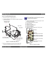
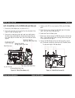
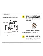
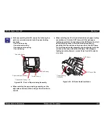
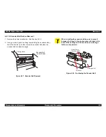
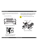
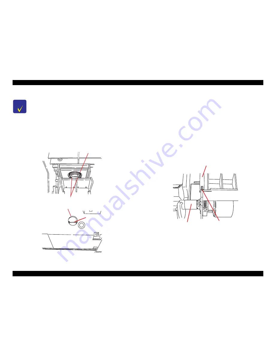
When installing the hopper assembly into the ASF
frame with the paper loading assemblies and LD roller
assemblies mounted on it, set the straight end (one of
the ends of each spring is bent straight) facing
upward. Then hook the straight end to the frame as
shown in the top figure below. After setting the
assembly, insert tweezers through the cutout in the
back of the ASF frame to release the straight end of
the compression spring as shown in the bottom figure
below.
Figure 4-30. Hopper Assembly Installation
C o m p r e s s i o n S p r i n g 1 . 6 6
H o o k s i n t h e F r a m e
C u t o u t i n t h e b a c k o f t h e A S F F r a m e
S t r a i g h t E n d o f t h e
C o m p r e s s i o n S p r i n g ( 1 . 6 6 )
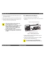
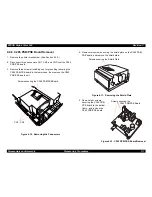
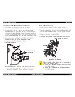
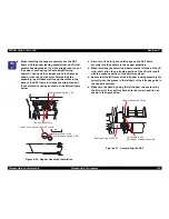
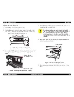
Be sure to fix both right and left pegs on the ASF frame
securely into the sockets in the hopper assembly.
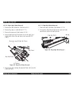
When installing the detection wheel onto the left end of the LD
roller shaft, align the protruding portion of the LD roller shaft
with the concave portion of the detection wheel.
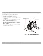
Ensure that the left frame of the left paper loading assembly fits
correctly into the groove in the left part of the left edge guide in
the hopper assembly.
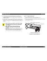
Make sure the bushing fixing the left hopper release lever by
the left part of the shaft is attached to the correct position as
shown in the figure below.
Figure 4-31. Assembling the ASF
H o p p e r A s s e m b l y G u i d e
L e f t F r a m e i n t h e
L e f t P a p e r L o a d i n g A s s e m b l y
B u s h i n g F i x i n g t h e S h a f t
Summary of Contents for Stylus Color 900
Page 1: ...EPSONStylusColor900 RevisionC Color ink jet printer SEIJ98006 ...
Page 8: ...Component Layout 180 Parts List 184 Exploded Diagrams 187 Circuit Diagrams 195 ...
Page 9: ... PRODUCTDESCRIPTION ...
Page 43: ... OPERATINGPRINCIPLES ...
Page 78: ... TROUBLESHOOTING ...
Page 101: ... DISASSEMBLYANDASSEMBLY ...
Page 130: ... ADJUSTMENT ...
Page 161: ... MAINTENANCE ...
Page 171: ... APPENDIX ...
Page 183: ...EPSON Stylus Color 900 Revision c Appendix Component Layout 183 Figure 7 6 C265 PNL Board ...
Page 194: ...06 03 01 02 for S E ASIA 03 03 05 03 04 EPSON STYLUS COLOR 900 No 7 10056 Rev 01 ...
Page 196: ......
Page 197: ......
Page 198: ......
Page 199: ......
Page 200: ......


