EPSON Stylus CX3100/3200
Revision A
Disassembly and Assembly
Disassembly Process
38
4.2 Disassembly Process
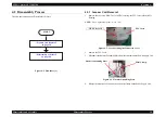
The flowchart below shows Disassembly Process
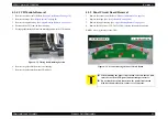
Figure 4-1. Flowchart (1)
4.2.1 Scanner Unit Removal
1.
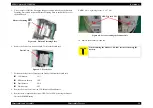
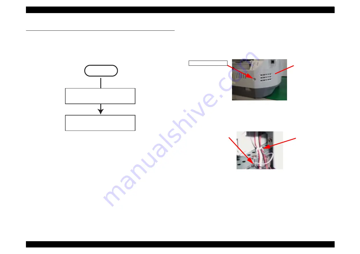
Remove the one screw (CBP-Tite 3x10 F/Zn) securing the FFC Cover to the Middle
Housing.
NOTE:
Screw tightening torque: 0.5 -0.7 Nm
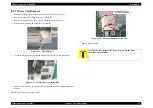
Figure 4-2. Screw securing the Connector Cover
2.
Remove the FFC Cover.
3.
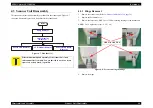
Disconnect the Harness Grounding Plate from the terminals on the Power Supply Unit.
Figure 4-3. Harness Grounding Plate
4.
Release the harness of the Scanner from the Mini Clamp on the Power Supply Unit.
START
CBP-Tite 3x10
FFC Cover
Harness Grounding Plate
Mini Clamp
Summary of Contents for Stylus CX3100
Page 1: ...EPSON StylusCX3100 3200 Scanner Printer Copier SERVICE MANUAL SEOT02002 ...
Page 5: ...Revision Status Revision Issued Date Description A Augusut 1 2002 First Release ...
Page 8: ...C H A P T E R 1 PRODUCTDESCRIPTION ...
Page 13: ...C H A P T E R 2 OPERATINGPRINCIPLES ...
Page 17: ...C H A P T E R 3 TROUBLESHOOTING ...
Page 34: ...C H A P T E R 4 DISASSEMBLYANDASSEMBLY ...
Page 57: ...C H A P T E R 5 ADJUSTMENT ...
Page 74: ...C H A P T E R 6 MAINTENANCE ...
Page 80: ...C H A P T E R 7 APPENDIX ...
Page 84: ......
Page 85: ......
Page 86: ......
Page 87: ......
Page 88: ......
Page 89: ...EPSON Stylus CX3100 3200 Revision A Appendix Exploded Diagrams 88 7 4 Exploded Diagrams ...
Page 90: ...EPSON Stylus CX3100 3200 Revision A Appendix ASP List 89 7 5 ASP List ...


