EPSON Stylus Photo 750
Revision A
Troubleshooting
Repair of the Control Board
45
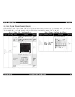
3.4 Repair of the Control Board
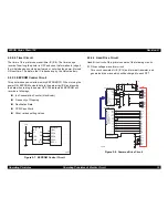
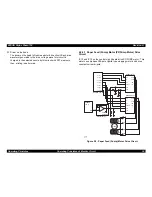
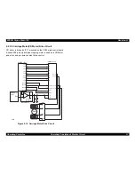
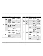
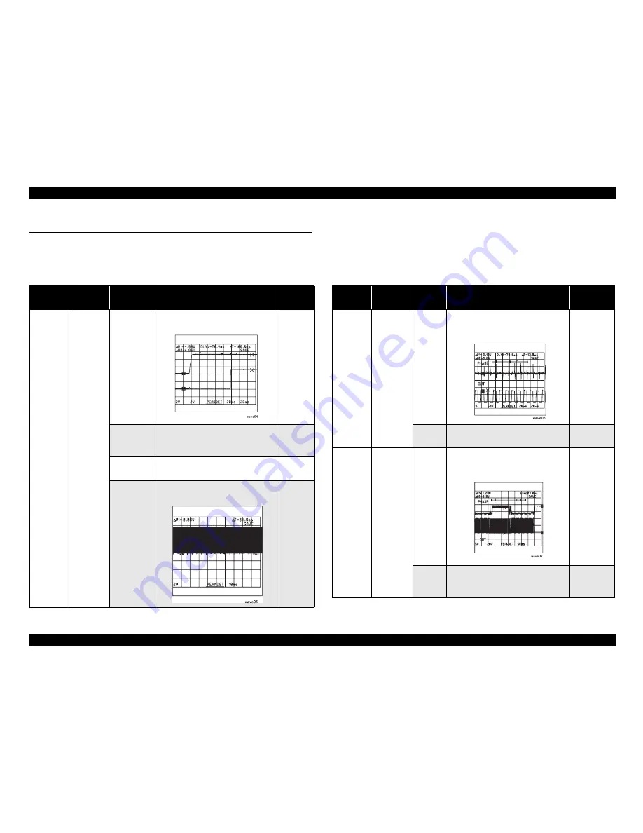
This section describes the problems related to the power supply board. The table below provides various symptoms, likely causes, and checkpoints.
The checkpoints refer to waveforms, resistance, and other values to check to evaluate the operation of each component.
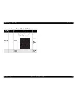
Table 3-7. Repair of the Control Board
Table 3-8. Repair of the Control Board
Sympto
m
Condition
Cause
Check point
Solution
The
printer
does not
operate at
all.
CPU does
not work.
Reset
circuit is
broken.
Check +5VDC line(Pin 7 of IC8) and
reset signal (Pin 2 of IC8).
Replace
IC8.
ROM is not
selected
correctly.
Check that the waveform of Pin 11
of IC3 reverses High/Low.
Replace
T1.
RAM is
broken.
Replace
Q1.
CPU is
broken.
Check the signal waveform Pin 88
of IC1.
Replace
Q2 or
Q3.
5VײÝ
/RESET
Sympto
m
Condition
Cause
Check point
Solution
Carriage
does not
operate
correctly.
CPU does
not work.
IC2 is
broken.
Check the PHASE(Pin 16 and 27) of
IC11 and signal waveform of
OUT(Pin 6,7, 8, and 9).
Replace
IC8.
IC14 is
broken.
Replace
IC11.
Abnormal
paper
feed.
PF motor
does not
rotate.
IC2 is
broken.
Check the PHASE(Pin 7) of IC 12
and 13, and signal waveform of
OUT(Pin 10 and 15).
If PHASE
signal is
not input,
replace IC.
IC12 &
13 are
broken.
Replace
IC12 or 13.
Summary of Contents for Stylus Photo 750
Page 1: ...EPSON Stylus Photo750 Color Inkjet Printer SEIJ98005 6 59 0 18 6 59 0 18 6 59 0 18 6 59 0 18 ...
Page 8: ... 3 7 5 4 PRODUCTDESCRIPTION ...
Page 32: ... 3 7 5 5 OPERATINGPRINCIPLES ...
Page 43: ... 3 7 5 6 TROUBLESHOOTING ...
Page 55: ... 3 7 5 7 DISASSEMBLYANDASSEMBLY ...
Page 81: ... 3 7 5 8 ADJUSTMENT ...
Page 95: ... 3 7 5 9 MAINTENANCE ...
Page 101: ... 3 7 5 APPENDIX ...
Page 111: ......
Page 112: ......
Page 113: ......
Page 114: ......

