EPSON Stylus Photo 750
Revision A
Disassembly and Assembly
Disassembly
56
C H E C K
P O I N T
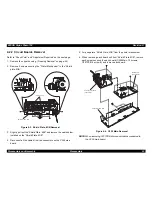
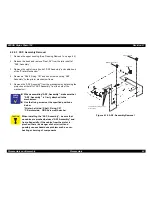
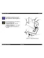
Unlock the connector CN6 and CN7 before
disconnecting them. Also, be sure to lock them when
reconnecting them.
A D J U S T M E N T
R E Q U I R E D
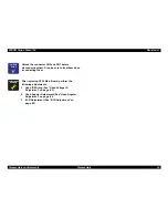
After replacing C259 Main Board, perform the
following adjustments.
1. Head ID Writing (See “Head Voltage ID
Adjustment” on page -83)
2. Head Angular Adjustment (See “Head Angular
Adjustment” on page -84
3. Bi-D Adjustment (See “Bi-D Adjustment” on
page -86)
Summary of Contents for Stylus Photo 750
Page 1: ...EPSON Stylus Photo750 Color Inkjet Printer SEIJ98005 6 59 0 18 6 59 0 18 6 59 0 18 6 59 0 18 ...
Page 8: ... 3 7 5 4 PRODUCTDESCRIPTION ...
Page 32: ... 3 7 5 5 OPERATINGPRINCIPLES ...
Page 43: ... 3 7 5 6 TROUBLESHOOTING ...
Page 55: ... 3 7 5 7 DISASSEMBLYANDASSEMBLY ...
Page 81: ... 3 7 5 8 ADJUSTMENT ...
Page 95: ... 3 7 5 9 MAINTENANCE ...
Page 101: ... 3 7 5 APPENDIX ...
Page 111: ......
Page 112: ......
Page 113: ......
Page 114: ......


