EPSON Stylus Pro 4400/4450/4800/4880/4880C
Revision C
Disassembly & Assembly
Disassembly Procedures
236
4.2.4.4 C511_SUB-B Board
1.
2.
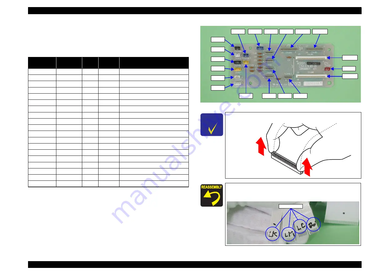
Disconnect all connectors/harnesses on the "C511_SUB-B Board".
Note 1: CN100, CN101 have connector lock mechanisms that must be released to
disconnect FFC. Refer to “Check Point“ on
Release the harness lock as shown
in the figure below. Be sure to lock it when reassembling. P.236
.
2: Refer to
for connector positions.
3: When connecting harnesses to the C511_SUB-B Board, connect them in the
order shown in
.
4: For the 4-color model, the CN39, CN42, CN43, CN45, and CN36 connectors
are not used.
Figure 4-44. C511_SUB-B Board Connector Positions
Table 4-7. Connectors/Harnesses Connected to C511_SUB-B Board
Connection
Order
Connector
No.
Color/
Mark
Number
of Pins
Connection Socket
1
CN103
-
17
Panel Unit (CN1)
2
CN46
-
7
Porous Pad Assy., Ink Eject
3
CN39
LK
7
CSIC_R1 Board (Light Black)
4
CN42
LC
7
CSIC_R2 Board (Light Cyan)
5
CN43
LM
7
CSIC_R3 Board (Light Magenta)
6
CN45
LLK
7
CSIC_R4 Board (Light Light Black)
7
CN22
Blue
2
P-Cover Open Sensor
8
CN36
White
2
I/H Lever Sensor (Right)
9
CN26
Black
2
Paper Eject Release Sensor
10
CN25
Red
2
ASF Paper Sensor
11
CN27
Yellow
2
Rear Hand Insertion Sensor
12
CN29
-
3
PE Sensor
13
CN31
Yellow
3
HP Sensor
14
CN33
White
3
P_THICK Sensor (0.3)
15
CN34
Black
3
P_THICK Sensor (0.8)
16
CN55
Blue
3
Pump Phase Sensor
17
CN102
-
17
C593 MAIN Board (CN48)
18
CN100
-
30
C593 MAIN Board (CN54)
19
CN101
-
30
C593 MAIN Board (CN51)
C H E C K
P O I N T
Release the harness lock as shown in the figure below.
Be sure to lock it when reassembling.
Each "Harness, CSIC" (CN39, CN42, CN43, CN45) is marked
with its corresponding ink name. Refer to
and
connect the harnesses properly.
CN36
CN34
CN31
CN29
CN33
CN26
CN22
CN55
CN27
CN39
CN42
CN103
CN102
CN45
CN43
CN46
CN101
CN100
CN25
Ink Names
Summary of Contents for Stylus Pro 4800 Portrait Edition
Page 9: ...C H A P T E R 1 PRODUCTDESCRIPTION ...
Page 113: ...C H A P T E R 2 OPERATINGPRINCIPLES ...
Page 156: ...C H A P T E R 3 TROUBLESHOOTING ...
Page 200: ...C H A P T E R 4 DISASSEMBLY ASSEMBLY ...
Page 366: ...C H A P T E R 5 ADJUSTMENT ...
Page 448: ...C H A P T E R 6 MAINTENANCE ...
Page 457: ...C H A P T E R 7 APPENDIX ...


