background image

EPSON COLOR INKJET PRINTER

Stylus Pro XL

SERVICE MANUAL

EPSON

4004677

Summary of Contents for Stylus Pro XL

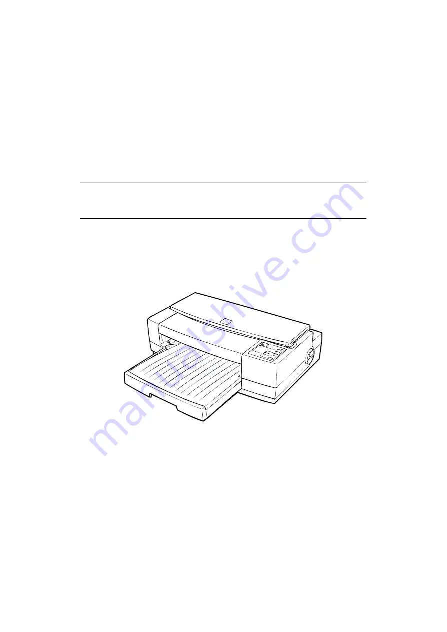
Page 1: ...EPSON COLOR INKJET PRINTER Stylus Pro XL SERVICE MANUAL EPSON 4004677 ...

Page 2: ...ecifications 1 10 1 3 2 Parallel Interface Specifications 1 12 1 4 OPERATIONS 1 13 1 4 1 Control Panel 1 13 1 4 2 Panel Operation at Power On 1 14 1 4 3 Default settings 1 15 1 4 3 1 Default Setting Items 1 15 1 4 3 2 Changing the Default Settings 1 16 1 4 4 Error Conditions 1 18 1 4 5 Printer Initialization 1 18 1 4 5 1 Hardware Initialization 1 18 1 4 5 2 Software Initialization 1 18 1 4 5 3 Pan...

Page 3: ...Printable Columns Table 1 3 Character Table Table 1 4 Cut Sheet Paper Specifications Table 1 5 Envelope Specifications Table 1 6 Adjust Lever Setting Table 1 7 Rated Electrical Ranges Table 1 8 Acceptable Environmental Conditions Table 1 9 Signal and Connector Pin Assignments for Parallel Interface Table 1 10 DTR and X ON X OFF Protocol Table 1 11 Signal and Connector Pin Assignments for Serial In...

Page 4: ... No dip switches Multi lingual setting messages 5 languages 4 scalable fonts and 5 LQ fonts standard Roman T Sans Serif H Roman Sans Serif scalable Roman Sans Serif Courier Prestige Script LQ 21 character tables Italic PC437 PC850 PC860 PC863 PC865 PC437 Greek PC852 PC853 PC858 PC857 PC866 PC869 PC861 BRASCII Abicomp MAZOWIA Code MJK ISO 8859 7 ISO Latin 1T Bulgaria Low running cost The figure bel...

Page 5: ...ial interface card C823071 C823081 32KB parallel interface card C82310 32KB IEEE 488 interface card C82313 LocalTalk interface card C82312 Twinax interface card C82315 Coax interface card C82314 The asterisk represents the last digit which varies by country Product Description Stylus Pro XL 1 2 Rev A ...

Page 6: ... Print speed See Table 1 2 Printable columns See Table 1 2 Table 1 2 Print Speed and Printable Columns Character Pitch Printable Columns Print Speed LQ 10 cpi Pica 127 200 cps 12 cpi Elite 152 240 cps 15 cpi 190 300 cps 17 cpi Pica condensed 218 340 cps 20 cpi Elite condensed 254 400 cps Row C Row D 2 3 7 6 62 63 1 360 20 360 2 0 3 60 72 360 1 Magenta Cyan Yellow 2 3 1 2 3 1 2 3 16 16 1 90 16 64 3...

Page 7: ...kish m PC866 Russian m PC869 Greek m MAZOWIA Poland m Code MJK Czecho Slovakia m ISO 8859 7 Greek m ISO Latin 1T Turkish m Bulgaria Bulgaria m Supported Not supported Fonts Bitmap LQ fonts EPSON Roman 10 cpi 12 cpi 15 cpi Proportional EPSON Sans Serif 10 12 15 Proportional EPSON Courier 10 12 15 EPSON Prestige 10 12 15 EPSON Script 10 12 15 Scalable fonts EPSON Roman 10 5 points 8 32 points in uni...

Page 8: ...14 0 in Letter 216 mm 8 5 in 279 mm 11 0 in A4 210 mm 8 3 in 297 mm 11 7 in Executive 184 mm 7 25 in 267 mm 10 5 in Statemrnt 140 mm 5 5 in 216 mm 8 5 in Thickness 0 08 mm 0 003 in 0 11 mm 0 004 in Weight 64g m2 17 lb 90 g m2 24 lb Quality Plain paper Special coated paper for 720dpi Special coated paper for 360dpi Transparency film High Quality Glossy paper Glossy paper Note Special coated paper f...

Page 9: ... size 9 mm 0 35 in Letter size 9 mm 0 35 in Letter size Landscape size 9 mm 0 35 in Executive size 9 mm 0 35 in Statement size 9 mm 0 35 in Envelopes 3 mm 0 12 in D The minimum bottom margin 14 mm 0 55 in Printable Area A Top Margin D Bottom Margin B Left Margin C Right Margin Figure 1 3 Printable Area for Cut Sheets B Left Margin C Right Margin A Top Margin D Bottom Margin Printable Area Figure 1...

Page 10: ... F Transit 120 hours or less at 60 C 140 F Dimension W D H 26 9 67 4 41 8 mm 1 06 2 65 1 65 in Color Type Exclusive cartridge Colors Cyan magenta yellow Print capacity 28 sheets color A4 or letter full image printing at 360 dpi Life The effective life from the indicated production date is 2 years Storage temperature 30 40 C 22 104 F Storage a month or less at 40 C 104 F 30 60 C 22 140 F Transit a ...

Page 11: ... Dielectric strength 1000 VAC rms 1 minute or 1200 VAC rms 1 second between AC line and chassis 1500 VAC rms 1 minute between AC line and chassis 1 2 6 Environmental Conditions Table 1 8 Acceptable Environmental Conditions Condition Operating Non Operating Temperature 10 35 C 50 95 F 1 20 60 C 4 122 F 2 Humidity 20 80 RH 1 3 5 85 RH 2 3 Shock resistance 1G within 1 msec 2G within 2 msec 2 Vibratio...

Page 12: ...22 2 950 with D3 220 240 V version EN 60950 TÜV SEMKO DEMKO NEMKO SETI Radio frequency interference RFI 120 V version FCC Part 15 Subpart B Class B 220 240 V version Vfg 243 VDE0878 part 3 part 30 EN55022 CISPR PUB 22 class B 1 2 9 Physical Specifications Dimensions W D H 580 597 182 mm 22 8 23 5 7 17 in Weight About 10 Kg 22 lb Stylus Pro XL Product Description Rev A 1 9 ...

Page 13: ...ns During data reception See Figure 1 7 When the input buffer is full When the INIT input signal is active During initialization When the ERROR or PE signal is active During the self test mode During the demonstration mode During the default setting mode When a fatal error occurs The ERROR signal is active LOW under the following conditions When a paper out error occurs When a no ink cartridge err...

Page 14: ... is ready to receive further data 11 BUSY O The BUSY signal informs the host computer of the printer s status When this signal is HIGH the printer cannot accept any more data 12 PE O This signal indicates whether paper is available in the printer or not A HIGH level indicates no paper 13 SLCT O Pulled up to 5 V through a 1 0 KΩ resistor in the printer 14 AFXT I If this signal is set to LOW the pri...

Page 15: ... none 1 bit Bit rate 57 6K bps 230 4 Kbps Adaptable connector 8 pin mini circular connector Recommended I F cable Apple System Peripheral 8 cable Table 1 11 Signal and Connector Pin Assignments for Serial Interface Pin No Signal Name I O Description 1 DTR Out Data terminal ready 2 NC No connection 3 TXD Out Transmit data 4 SG In Signal ground 5 RXD In Receive data 6 TXD Out Balanced transmit 7 NC ...

Page 16: ...tton causes the carriage to move to the gap adjustment position Pressing the Alt button again causes the carriage to return to the home position Economy Condensed Selects either economy or condensed printing mode Pressing the Economy Condensed button while holding down the Alt button starts the color printhead cleaning cycle Load Eject Either loads a new sheet into the printer or ejects paper curr...

Page 17: ...t buttons Once this mode is selected the printer prints all received data in hexadecimal format Demonstration mode Turn on the printer while holding down the Alt button Default setting mode Turn on the printer while holding down the Economy Condensed button For more information about the mode see Section 1 4 3 Initialize EEPROM Turn on the printer while holding the Alt Font Load Eject and Pause bu...

Page 18: ...I F mode Serial I F mode Optional I F mode Auto I F wait mode 10 30 seconds 10 sec Table 1 14 Characteristics of Print Direction Mode Mode Black and White Printing Color CMYK Printing Auto Throughput and quality is better Throughput is better Color quality with special paper is worse Color correction depends on the printing direction Bi D Throughput is best Print quality may be down Throughput is ...

Page 19: ...ed by the Courier Roman T PS and San Serif H PS LEDs Each time you press the Font button you adance to the next setting and the three font LEDs change according to the selection Table 1 17 Feature Selection Menu Setting Value Feature Menu Courier LED Roman T PS LED Sans Serif H PS LED Setting Operate LED Data LED Paper Out LED Character table On On On See Table 1 18 Print direction On Off Off Auto...

Page 20: ...865 Off On On PC861 On On On BRASCII Blinks On On Abicomp Off Blinks On NLSP PC437 Greek Off Off On PC853 Blinks Off On PC855 Off On On PC852 On On On PC857 Blinks On On PC866 Off Blinks On PC869 On Blinks On MAZOWIA Blinks Blinks On Code MJK Off Off Blinks ISO 8859 7 On Off Blinks ISO Latin 1T Blinks Off Blinks Bulgaria Off On Blinks 6 Repeat steps 4 and 5 to change other printer settings The set...

Page 21: ...nding the parallel interface INIT signal If the INIT signal is active when the printer is turned on hardware initialization is started when the INIT signal becomes inactive When the hardware initialization is performed The printer mechanism is initialized Input data buffer is cleared Downloaded character definitions are cleared Print buffer is cleared Default values are set 1 4 5 2 Software Initia...

Page 22: ...it CPU E05A96 gate array a program ROM 4M a dynamic RAM 4M a mask ROM 4M or 8M an EEPROM 1K and a lithium battery for powering the protect counters The reset IC M51955 and PST 592 is equipped with both a logic system and a power system The 8M program ROM is used only for the NLSP National Language Support Printer specification GA E05B09 IC2 CPU IC1 4M DRAMs IC5 6 Program ROM IC3 Mask ROM M160A69 I...

Page 23: ...gate array on the C162 MAIN Board and the logic system recognizes the power switch status 1 5 3 Control Panel C137 PNL Board The 14 LEDs on this board indicate the error status there is no buzzer system by using the 6 switches in combination with one another the printer can operate in each protect operation color or black cleaning cartridge exchanging self test default setting value exchanging res...

Page 24: ...nit and a color pump unit Waste ink from each printhead is made to flow into the individual caps Power for the pump system and paper feed system is supplied from the paper feed motor 1 5 5 Housing The Stylus Pro XL housing consists of the printer cover upper case and the lower case Attached to the housing are the front paper support and the ejected paper support with paper separator Figure 1 11 Pr...

Page 25: ...ING PRINCIPLES OF THE ELECTRICAL CIRCUITS 2 13 2 3 1 Operating Principles of the Power Supply Circuit 2 13 2 3 2 Operating Principles of the Main Control Circuit 2 15 2 3 2 1 Reset Circuit 2 16 2 3 2 2 Sensor Circuit 2 16 2 3 2 3 Carriage Motor Drive Circuit 2 17 2 3 2 4 Paper Feed Motor Drive Circuit 2 19 2 3 2 5 Printhead Drive Circuit 2 20 2 3 2 6 DMA Controller 2 22 2 3 2 7 D RAM Refreshment C...

Page 26: ... Block Diagram 2 16 Figure 2 19 Sensor Circuit Block Diagram 2 16 Figure 2 20 Carriage Motor Circuit Block Diagram 2 17 Figure 2 21 Serial Data Transfer Procedure 2 18 Figure 2 22 Paper feed Motor Drive Circuit Diagram 2 19 Figure 2 23 Normal Micro Dot Mode Switch Block 2 20 Figure 2 24 Trapezoidal Drive Wave Form 2 21 Figure 2 25 Printhead Drive Circuit Block Diagram 2 21 Figure 2 26 DMA Controll...

Page 27: ...omposed of the printhead unit paper feed mechanism carriage drive mechanism pump mechanism and various sensors The figure below shows a functional block diagram of the printer mechanism ASF Plunger Disengage Lever ASF Pickup Mechanism Paper Feed Mechanism Pump Unit Drive Mechanism Paper Feed Motor Carriage Motor Color Black Carriage Unit Figure 2 1 Printer Mechanism Block Diagram Stylus Pro XL Ope...

Page 28: ... pushes the vibration plate compressing the cavity for ink injection from the nozzle Cavity Ink supplied from the ink cartridge is stored in this space and is ejected fr om the nozzles when the vibration plate compresses this area Nozzles These eject ink against the paper s surface in response to the application of the print signal There are 64 black head or 48 color head individual nozzles making...

Page 29: ...ink charge or printhead cleaning operation is performed the ink in the cavity is vacuumed out with the pump mechanism During printing on the other hand the ink is simultaneously supplied from the ink cartridge and ejected from the nozzle according to the change of volume in the cavity A thermistor is attached to the side of the color printhead drive board to monitor the temperature because the vis...

Page 30: ... Dot Printing mode This printing mode can be selected by a command from the host computer Using the Micro Dot printing mode can improve the quality of output In Micro Dot Printing mode the ink dot size became to be smaller than the normal dot size Operating Principles Stylus Pro XL 2 4 REV A ...

Page 31: ...ption Motor Type 4 phase 200 pole hybrid type stepping motor Drive Voltage 35 VDC 5 Coil Resistance 10 0 Ω 7 Drive Frequency 960 4800 PPS Excitation Mode Constant current unipolar drive micro step drive In the following table 2 W1 2 phase means the 1 8 2 2 phase drive control Values in parentheses are for the 2 2 phase Table 2 2 Drive Terms CR Speed Frequency Phase Drive Method Acceleration Decele...

Page 32: ...e paper feed drive motor is a 4 phase 96 pole hybrid type stepping motor that directly drives the paper feed mechanism paper advancing operation paper pickup operation This motor also drives the pump mechanism but only when the printer is in the cleaning state The paper feed drive method is driven by the 2 2 phase drive method except the paper feed drive sequence 2 W1 2 phase Table 2 4 Paper Feed ...

Page 33: ...50 750 240 Paper feed 391 970 240 Pump drive 1 1800 1380 1380 1380 750 240 Pump drive 2 300 1380 240 PF Transmission Gear Quenching Roller PF Pinch Roller Unit Pickup Roller Paper PF Motor Pinion Gear Platen Drive Gear Paper Pickup Lever Tension Spring Plunger Hopper Frame Left Side Frame Figure 2 6 Paper Feed Mechanism Stylus Pro XL Operating Principles REV A 2 7 ...

Page 34: ...rain tank Wiping mechanism The figure below shows a diagram of the ink system Air Valve Black Head Color Head Pump 1 Pump 2 Ink Absorber Waste Ink Drain Tank Cleaning Blade for Color Black Head Pump Unit Friction Clutch Disengage Unit Platen Roller PF Motor Figure 2 7 Ink System Block Diagram Operating Principles Stylus Pro XL 2 8 REV A ...

Page 35: ...gram of the pump mechanism Pump system operation depends on the rotational direction of the paper feed drive motor as shown in Table 2 6 Drive Pump Mechanism Drive Switch Lever Set Platen Drive Gear Left Frame PF Motor Platen Carriage Hook Spring Sub Frame Disengage Lever Release Clutch Pump Unit Pump Drive Gear Right Frame Figure 2 8 Pump Mechanism Block Carriage D E Set Lever D E Reset Lever D E...

Page 36: ...Paper Feed Mechanism Switch Lever Reset Carriage Figure 2 10 Paper Feed Mechanism Block Diagram Carriage D E Reset Lever D E Lever Figure 2 11 Switch Lever Reset Operating Principles Stylus Pro XL 2 10 REV A ...

Page 37: ...squeezing the ink tube to push the ink inside the tube out to the waste ink drain tank When the motor rotates CCW backward the black pulley pumps in the wheel pump unit rotate in the direction of the arrow while squeezing the ink tube to push the ink inside the tube out to the waste ink drain tank There are two pump rollers in the pump unit and the drive power is supplied from the paper feed motor...

Page 38: ...mechanism cleans the surface of the printhead nose when the printer is in the ink system sequence The wiper drive gear transmits power from the paper feed motor via the clutch gear When the wiper is raised against the printhead surface the hook for securing the carriage to the home position is raised too When the wiper goes down toward the bottom frame the hook goes down too Both black and color h...

Page 39: ...by the C137 PSB Board 120 VAC or the C137 PSE Board 220 240 VAC Both boards are identical in design and functionality except for the components in the primary circuit that accommodate the specified input voltage The input voltage and the application of output voltages are summarized in the table below Table 2 7 DC Voltage Distribution Voltage Application 35 VDC Motor drive carriage and paper feed ...

Page 40: ...it through a photocoupler PC1 to stop the 35 V generation 2 5 VDC line over current over voltage control circuit The output current is monitored by a detection resistor R53 and fed back to the 5 VDC generation switching control IC IC51 which monitors the output voltage This information is input to the internal comparater and outputs the high signal to turn off the transistor Q51 when the voltage o...

Page 41: ... to store certain parameters such as the printer mechanism control parameter default setting parameters as well as a special counter value used for printhead ink management protection The timer IC NJU6355E IC7 counts each time the printer is cleaned and keeps track of how long the printer is not used thereby allowing the printer to be cleared only when necessary CLK SD I O DMAREQ DRAM 4M IC5 DRAM ...

Page 42: ... PE sensor The mechanical switch paper end PE sensor is built into the printer mechanism to determine whether there is paper in the printer or not A LOW level from the signal indicates that no paper is loaded BCO sensor CCO sensor The cartridge out CO sensor is micro switch attached to the bottom of each ink cartridge holder in the carriage unit When the ink cartridge is installed these switches a...

Page 43: ...our clock counts from the E05A96 IC2 clock Each bit is read at the falling edges of these clock pulses Due to this received serial data is placed in the shift register and then shifts the latch register When the STROBE pulse becomes active from the E05A96 IC2 the serial data is moved into the reference voltage selection circuit and the voltage is changed Therefore when the printer is in the consta...

Page 44: ...SLA7041MS 1 bit 2 bit 3 bit 4 bit Vref 5 V Vref STRB CLK a b c 1 bit 2 bit 3 bit 4 bit a b c Vref Voltage Selection Circuit To Motor Phase Signal Phase Latch 4 bit Serial Data 4 bit Shift Register Phase Reading of serial data from the Phase signal in order At this time the reference voltage selection circuit checks phase signal outputs Figure 2 21 Serial Data Transfer Procedure Operating Principle...

Page 45: ...hod is different for paper feed and the pump Table 2 9 Paper Feed Motor Drive Modes Mode Phase Excitation Drive Frequency Paper feed 2 2 phase or 2 W1 2 phase 391 or 1600 pps Pump drive 2 2 phase 300 or 1800 pps E05A96 IC2 41 40 43 4 2 PFB PFSTB CLKA 5 16 2 13 PFA SLA7041MS IC14 CLKB STBA STBB DATA A DATA B 6 17 PFVRF REF A REF B PFHLD RSA RSB 3 14 9 10 PFCLK PB8 PB13 B E C A A B B 1 8 11 18 1 2 3...

Page 46: ... latched data becomes 64 bit parallel data for the black head or 48 bit parallel data for the color head One bit corresponds to each nozzle When data transfer and nozzle selection is complete gate array E05A96 outputs the common drive pulse BPWC or CPWC charge pulse and BPWD or CPWD discharge pulse to the common drive circuit The common drive circuit then generates the trapezoidal pulse and applie...

Page 47: ...h Idle Pulse Pd Discharge Pulse Figure 2 24 Trapezoidal Drive Waveform E05A96 IC2 BPWC BPWD BLAT BCLK BCLKIN BSO CPWC CPWD CLAT CCLK CCLKIN CSO 1 3 1 4 1 9 1 8 1 7 2 0 1 5 1 6 2 3 2 2 2 1 2 4 COM1 8 COM1 6 SED5620D U1 C N 1 1 C N 1 68 L A T 69 67 C N 1 2 C N 2 CL K SI L A T CL K SI 68 69 67 DO6 4 49 DO4 8 33 DO32 17 DO16 1 DO6 4 49 DO4 8 33 DO32 17 DO16 1 C162 MAIN SED5620D U2 17 22 4 2 4 2 6 18 2...

Page 48: ...s the STBDMA strobe DMA request signal to the CPU When the CPU detects this signal the DMA controller in the CPU sends a bus request to the bus controller in the CPU and then the CPU releases the bus line Due to this external data is transported into the memory bypassing the CPU BAC DMAC BAREQ E05A96 IC2 STB STBDMA CPU H8 IC1 ACK BUSY DREQ1 9 129 DMARQ 128 14 DREQ2 166 161 162 Memory Figure 2 26 D...

Page 49: ...S DRAM CPU 2 CAS DRAM HWR UCAS LWR LCAS CS3 RAS RD WR The method of the DRAM refresh is used only for the CAS before RAS cycle method The following figure shows the timing for each cycle CA S RA S W E A S CA S RA S W E A S Read Cycle Write Cycle Read Write Cycle Refresh Cycle Figure 2 27 DRAM Cycle Timing CPU H8 IC1 DRAM IC5 CA S RA S W E O E 23 8 7 2 2 79 8 0 78 101 DRAM IC6 23 CS3 R D CAS RAS W ...

Page 50: ...Absorbing Cleaning Rubbing Operation Power Off Disengage On Print Start Disengage Off Refresh Micro Absorbing Standby Carriage Lock Set False Absorbing Carriage Lock Reset Ink Cartridge Replacement Refresh when loading or ejecting paper Forwarding not described These ink system operations are controlled by the following counters and timers Refresh Timer Monochrome Color Head Timer Flushing Counter...

Page 51: ...ormed when the printer receives print data while in the standby state 6 Refresh Operation This operation prevents an increase in the viscosity of the head ink 7 Standby Operation This operation prevents an increase in the viscosity of the head ink 8 False Absorbing Operation This operation absorbs ink inside the cap and eliminates ink from the nozzle plate 9 Ink Cartridge Replacement Operation Thi...

Page 52: ...s pauesd This operation is performed when the carriage is in the ink system home position and no paper is loaded 17 Carriage Lock Reset This operation resets the carriage lock lever 18 Refresh Operation Performed when Loading or Ejecting Paper This operation prevents an increase in the viscosity of ink inside the black head while paper is being loaded or ejected When paper is loaded or ejected jus...

Page 53: ...y sequence Values in parentheses mean only the color head 1 point 0 025 cc 1 Power On Micro 40 steps 6 5 2 points 40 steps 10 9 3 points 40 steps 15 12 5 4 points 2 CL 1 3600 4800 steps 16 20 points 40 steps 12 absorption 4 points 3 CL 2 720 steps 4 points 7800 8200 steps 40 points 40 steps 12 4 points 4 CL 3 40 steps 12 4 points 5 I C Replacement 8900 14000 steps 48 72 points 8900 8800 steps 48 4...

Page 54: ...emoval 3 5 3 2 4 Printer Mechanism M 4A60 Removal 3 7 3 2 5 Printer Mechanism Disassembly 3 8 3 2 5 1 Printhead Unit Removal 3 8 3 2 5 2 Carriage Unit Removal 3 12 3 2 5 3 Pump Unit Removal 3 13 3 2 5 4 Cleaner Head Replacement 3 14 3 2 5 5 CR Motor Removal 3 15 3 2 5 6 PF Motor Removal 3 15 3 2 5 7 Carriage Home Position HP Sensor Removal 3 16 3 2 5 8 Paper End PE Sensor Removal 3 16 3 2 5 9 Pape...

Page 55: ...on 3 11 Figure 3 11 Front Frame Removal 3 12 Figure 3 12 Carriage Unit Removal 3 12 Figure 3 13 Pump Unit Removal 3 13 Figure 3 14 Cleaner Head Replacement 3 14 Figure 3 15 CR Motor Removal 3 15 Figure 3 16 PF Motor Removal 3 15 Figure 3 17 HP Sensor Removal 3 16 Figure 3 18 PE Sensor Removal 3 16 Figure 3 19 Tension Roller Assembly Removal 3 17 Figure 3 20 Paper Feed Roller Assembly Removal 3 17 ...

Page 56: ...er on any part of the battery Doing so may result in leakage of electrolyte from the battery burning or explosion The leakage may affect other devices close to the battery 4 Do not charge the battery An explosive gas may be generated inside the battery and cause burning or explosion 5 Do not dismantle the battery The gas inside the battery may hurt your throat Leakage burning or explosion may also...

Page 57: ...6 3 2 5 7 8 3 2 5 9 3 2 5 10 Upper Case Removal Page 3 3 Power Supply Unit Removal Page 3 4 Main Controller Removal Page 3 5 Printer Mechanism Removal Page 3 7 Printhead Unit Removal Page 3 8 Carriage Unit Removal Page 3 12 Pump Unit Removal Page 3 13 Clerner Head Removal Page 3 14 CR Motor Removal Page 3 15 PF Motor Removal Page 3 15 HP PE Sensor Removal Page 3 16 Removal Page 3 17 Upper Frame Re...

Page 58: ...the upper case as shown in the figure below At this time disconnect the connector on the C137 PNL Board 5 Remove the 2 CBB M3 11 screws securing the upper case to the lower case 6 Release 1 tab by inserting a flathead screwdriver into the holes at the bottom of the lower case as shown in the figure below 7 Remove the upper case by lifting the front side At the same time release 1 tab located in th...

Page 59: ...he lower case and remove a CBN O M3 6 screw fixing the earth line from the AC cable to the earth plate 5 Remove the wire harness for the motors in the locking tab on the shield plate and take the shield plate out by pulling upward toward the back of the printer 6 Remove the power supply unit by pulling it upward toward the back of the printer CAUTION The shield plates of C137 PSB PSE and C162 MAIN...

Page 60: ...s securing the Type B interface cover to the lower case 5 Disconnect the cables from connectors CN5 CN6 CN7 CN8 CN9 CN10 CN11 CN12 and CN13 of the C162 MAIN Board 6 Remove the 4 CBB screws 2 M3 12 and 2 M3 8 securing the main controller to the lower case and then remove the C162 MAIN Board CBB M3x12 CBB M3x12 CBS M3x8 Grounding Plate Grounding Plate Shield Plate Figure 3 5 Main Controller Removal ...

Page 61: ...es pin 1 of CN6 CN7 Paper feed motor cable black mark the black mark indicates pin 1 of CN7 REQUIRED ADJUSTMENT When replacing the main controller board adjust both the head gap and the bidirectional adjustment alignment and save the adjusted parameters into the EEPROM on the C162 MAIN Board See Chapter 4 When you replace the main board the parameters in the internal timer are all reset Therefore ...

Page 62: ...place the printhead or printer mechanism you must replace the block resistor at location RM4 for Micro Mode Color R No RM5 for Normal Mode Color M No RM11 for Micro Mode Monochrome R No and RM12 for Normal Mode Monochrome M No on the C162 MAIN Board Every spare printhead or spare printer mechanism comes with a block resistor that is specifically selected for each printhead Refer to Table 3 1 Adjus...

Page 63: ...lly The exclusive cartridge is Monochrome 1020626 YMC 1020627 Ink cartridges should never be kept longer than 6 months 4 Push the 2 hooks from the inside of ink cartridge holder with tweezers and push down the ink cartridge clamp monochrome color to remove the clamps from ink cartridge holder 5 Remove the 3 CBB M3 11 screws and 3 plain washers securing the ink cartridge holder to the carriage base...

Page 64: ...Pull the black or color head toward you and disconnect the head FFC cable on the head driver board nozzle selector Then remove the black or color head Color Head Black Head Figure 3 9 Printhead Removal Rubber Cap Head Fixing Sczew CBB M3x11 CBB M3x11 Figure 3 8 Ink Cartridge Holder Removal Stylus Pro XL Disassembly and Assmbly REV A 3 9 ...

Page 65: ...lock resistor at location RM4 for Micro Mode Color R No RM5 for Normal Mode Color M No RM11 for Micro Mode Monochrome R No and RM12 for Normal Mode Monochrome M No on the C162 MAIN Board Every spare printhead or spare printer mechanism comes with a block resistor that is specifically selected for each printhead Refer to Table 3 2 Table 3 2 Insertion Location of the Block Resistors Mode Head Indica...

Page 66: ...nt adjustment see Section 4 1 2 When removing or changing both heads the following adjustments are needed 1 Color head angle adjustment see Section 4 1 6 2 Black head angle adjustment see Section 4 1 4 3 Black Color head vertical adjustment see Section 4 1 5 4 Head gap adjustment see Section 4 1 3 5 Bidirection alignment adjustment see Section 4 1 2 WARNING When removing the color or black head do...

Page 67: ...from both side frames 8 Lift the carriage unit with the carriage guide shaft out of the printer mechanism CAUTION Take proper measures to protect the printhead unit from static electricity because the driver IC is directly attached to the printhead unit Never touch the printhead s metallic nozzle cover surface Handle it only by holding the edges of the printhead When you replace the printhead or t...

Page 68: ...2 3 Remove the CBS M3 6 screw securing the pump unit to the bottom frame 4 Push the pump unit outward while releasing the tab at the bottom side of the pump unit and then lift up the pump unit CBS M3x6 Bottom Frame Pump Unit 1 2 2 Figure 3 14 Pump Unit Removal Disassembly and Assembly Stylus Pro Service Manual 3 12 Rev A ...

Page 69: ...jection system working properly in the printhead and it directly affects printing quality Therefore handle the cleaner head very carefully and observe the following precautions Never touch the cleaner head with your bare hands When attaching the cleaner head to the pump unit wear gloves and use clean tweezers to handle it Cleaner Head Cleaner Lever Hook Figure 3 14 Cleaner Head Replacement Disasse...

Page 70: ...securing the CR motor to the upper frame and then remove the CR motor 3 2 5 6 PF Motor Removal 1 Remove the printer mechanism see Section 3 2 4 2 Remove the 2 CBN M3 6 screws and then remove the PF motor CR Motor Screws Figure 3 15 CR Motor Removal CBS M3x6 PF Motor Figure 3 16 PF Motor Removal Stylus Pro XL Disassembly and Assmbly REV A 3 15 ...

Page 71: ... 5 8 PE Sensor Removal 1 Remove the printer mechanism See Section 3 2 4 2 Disconnect the connector for the PE sensor 3 Rotate the printer mechanism upside down use tweezers to release the 2 hooks securing the PE sensor to the paper feed roller assembly Then remove the PE sensor Sensor Cable Carriage Home Position Sensor Figure 3 18 Carriage Home Position Sensor Removal Sensor Cable PE Sensor Botto...

Page 72: ...assembly to the left side frame 6 Remove a CBB M3 8 screw securing the tension roller assembly to the sub frame and remove the tension roller assembly 7 Release the 2 bushings securing the paper feed roller assembly to both the left side frame and the sub frame Then remove the paper feed roller assembly CBB M3x8 Tension Wire Tension Roller Assembly Eject Paper Roller Tension Wire Figure 3 19 Tensi...

Page 73: ... upper frame to both side frames or the sub frame Then remove the upper frame with 4 PF support rollers 5 Remove the upper frame with 4 PF support rollers ASSEMBLY POINT Assemble each straight end of torsion spring 6700s to attach to the center of the driven roller support CBS M3x5 CBS M3x5 Knob Tension Spring E ring Upper Frame Figure 3 21 Upper Frame Removal Base Frame PF Support Roller Tension ...

Page 74: ...ustment Sample 4 6 Figure 4 5 Spacer Slection 4 6 Figure 4 6 Removing the Rubber Cap 4 7 Figure 4 7 Spacer Angular Replacement Method 4 8 Figure 4 8 Black Color Head Vertical Adjust Conception 4 9 Figure 4 9 Spacer Linear Selection Sample 4 9 Figure 4 10 Removing the Rubber Cap 4 10 Figure 4 11 Spacer Linear replacement Method 4 11 Figure 4 12 C Head Angle and Spacer Angular Position 4 12 Figure 4...

Page 75: ...he M 4A60 printer mechanism 1 Bi D alignment adjustment see Section 4 1 2 2 Head gap adjustment see Section 4 1 3 3 Internal timer reset operation see Section 4 1 8 When replacing or disassembling the C162 MAIN board or printer mechanism 1 Destination data writing operation see Section 4 1 1 2 Bi D alignment adjustment see Section 4 1 2 3 Head gap adjustment see Section 4 1 3 When replacing or dis...

Page 76: ...etting 2 Head Angle Confirmation Pattern Printing Black Head Spacer Selection 3 Head Vertical Position Confirmation 4 Head Gap Adjustment 5 Bi D Adjustment 6 Internal Timer Reset 7 END 3 When the main menu appears choose Destination Setting by typing 1 and Enter 4 The main menu immediately disappears briefly and then reappears At this time specific destination parameters including the destination ...

Page 77: ...ttern Printing Black Head Spacer Selection 3 Head Vertical Position Confirmation 4 Head Gap Adjustment 5 Bi D Adjustment 6 Internal Timer Reset 7 END 3 When the main menu appears choose Bi D Adjustment by typing 5 and ENTER The printer prints a check pattern with a sample compensation value 4 The next menu appears on the display Input Bi D value No 30 No 30 If O K input Y key _ 5 If the sample pri...

Page 78: ...by typing 4 and ENTER The printer prints a check pattern with a sample compensation value 4 The printer prints a sample like the one shown in Figure 4 1 5 If the sample print is not vertically aligned for both odd numbered lines black lines and even numbered lines magenta lines enter a compensation value in the range from 16 to 16 Positive compensation value Shifts the 2nd line to the left Negativ...

Page 79: ...ows the relationship between the shape and thickness Black Head Angle Adjustment Concept Black Head Reverse Side Head Base Carriage Angular Spacer Linear Spacer Spacer Setting Position Figure 4 2 Black Head Angular and Linear Spacers 0 05 0 10 0 15 0 20 0 25 0 05 0 12 0 19 0 26 0 33 0 47 0 54 0 61 0 68 0 75 0 40 Angular Spacers For Black Head Linear Spacers Only Use for Black Head Spacer Name Spac...

Page 80: ...u replace the black head and print the black head angle pattern you only have to insert an angular spacer if the pattern is incorrect 4 The printer prints a pattern like one in the following sample Only the nozzles in rows A and D are fired making it is easy to see the angle of the black head 5 In the figure above pay attention to position A Do not look at position B 6 Using the following flowchar...

Page 81: ...re returning the printer to the user During this adjustment use ink cartridges exclusively for service Monochrome 1020626 CMY 1020627 You can reuse old ink cartridges for other purposes 10 Replace the angular spacer for the black head with a new one referring Figure 4 7 Replace the angular spacer by using tweezers to push the head base toward the rear 1 Push Carriage Unit Platen Gap Adjust Lever L...

Page 82: ...in until the head angle is correct WARNING The angular spacer comes in five thicknesses Continue performing this adjustment by changing the black head angle is correct When inserting an angular spacer always place the angular spacer on the linear spacer 1 Push Carriage Unit Platen Gap Adjust Lever Linear Spacer Black Head Head Base Angular Spacer 2 Replace Angular Spacer Replacement Position Figur...

Page 83: ...Pattern Printing Black Head Spacer Selection 3 Head Vertical Position Confirmation 4 Head Gap Adjustment 5 Bi D Adjustment 6 Internal Timer Reset 7 END 3 When the main menu appears choose Head Vertical Position Confirmation by typing 3 and ENTER The printer prints the check pattern along with the sample name WARNING When replacing the black head always adjust the black head angle first because the...

Page 84: ... necessary replace the linear spacer For instance if your pattern is similar to the pattern shown under 2 replace the linear spacer with a thinner linear spacer If your pattern is similar to the pattern shown under 2 replace the linear spacer with a thicker spacer 5 Turn the printer off 6 Move the carriage to the center while pressing the carriage lock lever and remove the two ink cartridges 7 Rem...

Page 85: ...ample print is correct If the sample is incorrect change the thickness of the linear spacer and perform this adjustment again until the two black and magenta lines are aligned at the position OK 0 10 When you complete this adjustment exit the BASIC program and turn off the printer 1 Push Carriage Unit Platen Gap Adjust Lever 2 Replace Black Head Head Base Linear Spacer x 2 Linear Spacer Replacemen...

Page 86: ...arget printer and turn the printer on 2 Execute BASIC on the PC and run the program VERxxx BAS 1 Destination Setting 2 Head Angle Confirmation Pattern Printing Black Head Spacer Selection 3 Head Vertical Position Confirmation 4 Head Gap Adjustment 5 Bi D Adjustment 6 Internal Timer Reset 7 END 3 When the main menu appears choose Head Angle Confirmation Pattern Printing by typing 2 and ENTER The pr...

Page 87: ...t procedure is explained beginning in step 5 5 Turn off the printer now 6 Move the carriage to the center manually and loosen but do not remove the screw securing the color head to the carriage 0 30 0 35 0 40 0 45 0 50 Angular Spacer for Color Head Spacer Name Thickness Shape angular spacer YMC angular spacer YMC B angular spacer YMC C angular spacer YMC D angular spacer YMC E Figure 4 14 Relation...

Page 88: ...e 3 screws Refer to the figure below 8 Replace the angular spacer on the left side with a new one referring the figure below Replace the angular spacer using tweezers to push the head base toward the rear Rubber Cap Screw 1 Screw 2 Screw 3 Figure 4 16 Removing the Rubber Cap Adjustments Stylus Pro XL 4 14 Rev A ...

Page 89: ...the upper lines in the sample are aligned with one another and the lower lines in the sample are exactly equidistant to one another as shown at B in Figure 4 15 11 When you complete this adjustment turn off the printer 1 Push Carriage Unit Color Head 2 Replace Angular Spacer one side only Platen Gap Adjust Lever Head Base Figure 4 17 YMC Angular Spacer Replacement Stylus Pro XL Adjustments Rev A 4...

Page 90: ...kness gauge 4 After attaching the printheads to the gauge surface verify that the gap between the carriage roller and the front frame is less than 0 04 mm See Figure 4 16 5 Attach the 1 1 mm thickness gauge to the right side adjustment position on the paper guide plate as shown below so that one side hooks the paper feed pinch roller unit Note When checking the gap between the carriage roller and ...

Page 91: ...er and turn on the printer 2 Execute BASIC on the PC and run the VERxxx BAS program 1 Destination Setting 2 Head Angle Confirmation Pattern Printing Black Head Spacer Selection 3 Head Vertical Position Confirmation 4 Head Gap Adjustment 5 Bi D Adjustment 6 Internal Timer Reset 7 END 3 When the main menu appears choose Internal timer reset by typing 6 and ENTER This resets the internal timer The fo...

Page 92: ...l 5 8 5 3 UNIT REPAIR C137 PSB PSE BOARD 5 9 5 4 UNIT REPAIR C164 MAIN BOARD 5 10 5 5 UNIT REPAIR PRINTER MECHANISM M 4A11 5 12 LIST OF FIGURES Figure 5 1 Troubleshooting Process Flowchart 5 1 LIST OF TABLES Table 5 1 Motor Coil Resistance Test Points 5 1 Table 5 2 Sensor Status 5 1 Table 5 3 Sensor Test Points 5 2 Table 5 4 Error Codes 5 2 Table 5 5 Symptoms and Problems 5 3 Table 5 6 Repair of t...

Page 93: ...Rev A 5 i ...

Page 94: ...8 Pin 1 PE to Pin 2 GND H 5 V Paper exists L GND No paper paper end BCO Sensor CN11 Pin 8 BCO to Pin 7 GND L GND Black cartridge exists H 5 V No black cartridge CCO Sensor CN12 Pin 8 CCO to Pin 7 GND L GND Color cartridge exists H 5 V No color cartidge HP Sensor CN9 Pin 3 HPV to Pin 2 GND L At home position HP H Out of HP TH Sensor CN10 Pin 10 SW0 5 to Pin 1 GND Analog data Change the pulse width ...

Page 95: ...cartridge On On Install the new ink cartridge and press the Pause button Paper jam Blinks Load paper and press Pause and Load Eject buttons Maintenance request Blinks Blinks Blinks Blinks Blinks Blinks Service maintenance request Change the waste ink drain tank and reset the counter Carriage error Blinks Blinks Turn off the printer and turn it on again Troubleshooting Stylus Pro XL 5 2 Rev A ...

Page 96: ... Flowchart No Printer does not operate at power on LEDs do not light up Printer mechanism does not operate 5 2 1 Error is detected Error is indicated by LED indication 5 2 2 Failure occurs during printing Printing is not performed Abnormal printing missing dots etc Print quality is poor 5 2 3 Printer does not feed the paper correctly No paper is fed Paper feed is irregular Paper jam occurs 5 2 4 C...

Page 97: ...n Replace the fuse and disconnect CN5 on the C162 MAIN board Check the output voltage of the C137 PSB PSE at CN2 Does the fuse blow again at power on Is the output voltage correct Replace the C162 MAIN board Replace the C137 PSB PSE board Is the problem corrected Check motors and drivers Refer to the section describing repair of the printer mechanism Troubleshooting Stylus Pro XL 5 4 Rev A ...

Page 98: ...No ink cartriage Replace the ink cartridge with a new one Check CR motor and drivers If they are OK replace the C162 MAIN board Waste ink drain tank overflow Replace the waste ink absorbing material and reset the protect counter See Chapter 6 Check ink cartridge sensor and if bad replace Refer to the section describing repair of the printer mechanism Is the problem corrected Does error occur again...

Page 99: ...nt alignment or readjust the head arrangement adjustment See Chapter 4 See the section describing repair of the printer mechanism Check all motors drivers and printhead for shorts If they are OK replace the C162 MAIN board Is the problem corrected Is print quality bad Does the self test print Is the problem corrected Is the problem corrected Are all cables connected to the C162 MAIN board firmly T...

Page 100: ...lear Also confirm that there are no foreign objects that may interfere with paper movement Check the PF motor and driver If OK replace the C162 MAIN board Perform the PF roller cleaning with the cleaning sheet See the section describing repair of the printer mechanism Does a paper jam occur Is the problem corrected Is the problem corrected Is the problem corrected Stylus Pro XL Troubleshooting Rev...

Page 101: ...ND YES YES N O N O END YES N O Connect the control panel correctly Replace the control panel Replace the C162 MAIN board Is the control panel connected properly Is the problem corrected Is the problem corrected Troubleshooting Stylus Pro XL 5 8 Rev A ...

Page 102: ...ce Q1 35 V line is abnormal ZD52 Q83 or PC1 is dead Check the voltage level of the collector side The correct voltage is as follows Power Switch Off 1 8 VDC Power Switch On 0 VDC Replace ZD52 Q82 or PC1 5 V line is dead 35 V line is dead Check the 35 V line Replace IC51 IC51 is dead Check the oscillation waveform and switching waveform of IC51 Oscillation waveform IC51 pin 5 Switching waveform IC5...

Page 103: ...you turn the printer on or off The reset circuit does not operate Check the waveform of the 5 V line and that of the RESET signal Replace IC13 or IC8 Selection of control ROM is abnormal Check pin 2 of IC3 for a change in the signal HIGH LOW Replace IC1 Either CG or RAM is defective Replace CG or RAM CPU is defective Check the oscillator signal at either pin 75 or 74 of the CPU If signal is detect...

Page 104: ... Self test is not executed IC2 is defective Check the output signal at pin 13 or 14 and pin 15 or 16 of IC2 Replace IC2 Printhead unit is defective Replace printhead unit Paper feed does not operate normally The paper feed motor does not rotate IC2 is defective Check the serial signals output from pins 39 or 40 of IC2 to the driver IC14 Replace IC2 IC14 is defective Check the output signal at pin ...

Page 105: ...to be absorbed normally Replace the pump unit The printhead is defective Replace the printhead to see if this causes the ink to be absorbed normally Replace the printhead The carriage motor does not rotate The carriage motor fails to rotate at power on Foreign substances are lodged in the gear of the mechanism Manually drive the timing belt to see if the carriage motor rotates Remove any foreign s...

Page 106: ...clean Check the front of the printhead Clean The ink cartridge is used up Check whether the ink cartridge is empty Replace the ink cartridge Insufficient head cable contact Check whether the cable is properly plugged into the connector Plug the cable into the connector properly Check whether the printhead is clean Clean The printhead is defective Replace the printhead to see if this causes printin...

Page 107: ...tive gears The paper feed motor is defective Measure the coil resistance of the PF motor Replace the PF motor Paper top of form position slips comes out too narrow Particles of power residue from coating on glossy paper are sticking to the PF roller Check that particles of the power residue from the coating on glossy paper are not sticking to the PF roller Perform the PF roller cleaning with the c...

Page 108: ... Cleaning 6 2 6 2 2 Waste Ink Drain Tank Replacement 6 2 6 3 LUBRICATION AND ADHESIVE 6 3 LIST OF FIGURES Figure 6 1 Lubrication Points and Adhesive Points 1 6 5 Figure 6 2 Lubrication Points and Adhesive Points 2 6 6 LIST OF TABLES Table 6 1 Recommended Lubricants 6 3 Table 6 2 Lubrication and Adhesive Points 6 3 ...

Page 109: ...of the printer CAUTION Do not use a hard or abrasive brush for cleaning Be careful not to damage the components of the printer when using a vacuum cleaner A lithium battery is installed on the C164 MAIN board of this printer Be sure to observe the following instructions when servicing the printer or storing the after service parts 1 Keep the battery away from any metal or other batteries so that e...

Page 110: ... panel button operation is accepted by the printer the PAUSE LED flashes during the cleaning cycle When the cleaning completes the PAUSE LED stops flashing and the printer returns to standby mode 6 2 2 Waste Ink Drain Tank Replacement The printer counts the total amount of ink drained to the waste ink drain tank and this information is stored in the EEPROM on the main board in Protect Counter A Th...

Page 111: ...embly 8 Contact surface of the right side of the front paper guide and the eject roller assembly G 36 1 3 mg 9 Right end point of the eject roller assembly G 20 1 3 mg 10 Contact surfaces of the shaft and combination gear 13 5 22 and the combination gear holder on the sub frame assembly G 36 1 3 mg 11 The teeth of gear 22 5 G 36 1 3 mg 12 The teeth of combination gear 28 17 5 14 End points of the ...

Page 112: ...CAUTION Do not apply too much lubricant as it may stain the mechanism as well as a cause a mechanism malfunction Maintenance Stylus Pro Service Manual 6 4 Rev A ...

Page 113: ...2 1 17 17 22 30 21 27 9 8 7 4 4 6 5 11 12 20 Figure 6 1 Lubrication Points and Adhesive Points 1 Stylus Pro Service Manual Maintenance Rev A 6 5 ...

Page 114: ...16 3 19 18 18 14 14 28 10 3 1 1 2 2 1 1 2 2 Lubrication Point Adhesive Point Figure 6 2 Lubrication Points and Adhesive Points 2 Maintenance Stylus Pro Service Manual 6 6 Rev A ...

Page 115: ...6 Figure A 11 C137 PNL Board Component Layout A 17 Figure A 12 Exploded Diagram for Stylus Pro XL 1 A 18 Figure A 13 Exploded Diagram for Stylus Pro XL 2 A 19 Figure A 14 Exploded Diagram for Stylus Pro XL 3 A 20 List of Table Table A 1 Connector Summay A 2 Table A 2 Connector Pin Assignments CN1 A 2 Table A 3 Connector Pin Assignments CN2 A 3 Table A 4 Connector Pin Assignments CN3 A 3 Table A 5 ...

Page 116: ... PSE C137 PNL C162 MAIN CN1 CN5 CN11 CN9 CN8 CN7 CN6 CN10 CN2 CN1 CN CN 2 CN3 CN12 CN CN13 AC Input Parallel I F Type B Parallel I F RS 422 Serial I F PF Motor CR Motor ASF Plunger Printhead Unit HP Sensor CR Sensor Printer Mechanism M 4A60 Color Black Figure A 1 Interconnection of Major Components Stylus Pro XL Appendix Rev A A 1 ...

Page 117: ...Color head nozzle selector and common driver CN13 2 ASF plunger C137 PSB PSE CN1 2 AC inlet L N CN2 8 DC output 5 V 35 V C137 PNL CN1 20 to C162 MAIN Table A 2 Connector Pin Assignments CN1 Pin I O Name Description 1 I STB Strobe signal 2 9 I DATA1 8 Data strobe signal 10 O ACK ACK signal 11 O BUSY Busy signal 12 O PE Paper end signal 13 O SLCT Printer select signal 14 I AFXT Auto line feed signal...

Page 118: ...select signal 19 24 GND Ground 25 28 I O A3 A0 Address bus signal 3 0 29 36 I O D15 D8 Data bus signal 15 8 Table A 4 Connector Pin Assignments CN3 Pin I O Name Description 1 DTR Data terminal ready 2 NC Not connected 3 O TXD Transmit data 4 GND Ground 5 I RXD Receive data 6 O TXD Transmit data 7 NC Not connected 8 I RXD Receive data There is no connector CN4 Table A 5 Connector Pin Assignments CN...

Page 119: ...ommon voltage Table A 8 Connector Pin Assignments CN8 Pin I O Name Description 1 I PE Paper on out state detection signal 2 GND Ground Table A 9 Connector Pin Assignments CN9 Pin I O Name Description 1 I HP Home position detection signal 2 GND Ground 3 O HPV Sensor drive power supply Table A 10 Connector Pin Assignments CN10 Pin I O Name Description 1 3 5 7 GND Ground 2 O LDATA LED data 4 O LCLK C...

Page 120: ...rinthead drive Table A 12 Connector Pin Assignments CN12 Pin I O Name Description 1 GND Ground 2 O CCLK Clock signal for color head 3 GND Ground 4 O CLAT Latch signal for color head 5 GND Ground 6 O CSI Color head serial data output 7 GND Ground 8 O CCO Color cartridge out sensor 9 I 5 V Power supply for cartridge out sensor 10 I TH Thermistor signal 11 16 O GP Ground 18 22 O COM Common voltage fo...

Page 121: ...BOARD GUIDE GUIDE I F BOARD 120 UPPER CONNECTOR COVER COVER CONNECTOR UPPER 121 CLAMP CLAMP 122 CBB SCREW M3 12 C B B SCREW M3 12 123 CBS TITE SCREW M3 12 C B S TITE SCREW M3 12 124 CBS SCREW M3 8 F UC C B S SCREW M3 8 F UC 125 CB O SCREW M4 8 C B O SCREW M4 8 126 HEXAGON NUT M4 HEXAGON NUT M4 127 CB USCA 3 6 F ZN C B USCA 3 6 F ZN 128 CB SCREW 4 14 F ZN C B SCREW 4 14 F ZN 129 CBB SCREW M3 10 C B...

Page 122: ...V 240 VAC INLET HARNESS 220V 240V AC INLET 450 PANEL BOARD BOARD ASSY PANEL 500 PRINTER MECHANISM M 4A60 PRINTER MECHANISM M 4A60 501 DRIVEN PULLEY PULLEY DRIVEN 502 BASE FRAME FRAME ASSY BASE 503 PE DETECTOR 0 V 0 A 0 W DETECTOR PE 0V 0A 0W 504 LEFT FRAME FRAME ASSY LEFT 505 MIDDLE FRAME FRAME ASSY MIDDLE 506 RIGHT MAIN FRAME FRAME MAIN RIGHT 507 BOTTOM MAIN FRAME FRAME MAIN BOTTOM 508 CARRIAGE B...

Page 123: ...R LEVER KNOB 539 CR STEPPING MOTOR 4 0 VDC 0 4 A STEPPING MOTOR CR DC 4 0V 0 4A 540 CR COVER B COVER ASSY CR B 541 CR GUIDE GROUNDING SPRING GROUNDING SPRING CR GUIDE 542 CR STOPPER LEVER LEVER CR STOPPER 543 CR DAMPER DAMPER CR 544 CR DAMPER SHAFT B SHAFT DAMPER CR B 545 PAPER LOAD LEVER LEVER PAPER LOAD 546 DRIVEN ROLLER ROLLER DRIVEN 547 DRIVEN ROLLER HOLDER HOLDER ROLLER DRIVEN 548 DRIVEN ROLL...

Page 124: ...ANTI STATIC BRUSH ANTI STATIC BRUSH 581 PAD HOLDER C HOLDER ASSY PAD C 582 EDGE GUIDE EDGE GUIDE 583 EDGE GUIDE PRESSING PLATE PRESSING PLATE EDGE GUIDE 584 HOPPER HOPPER ASSY 585 PAPER LOADING CORK CORK PAPER LOAD 586 GEAR CHANGE GUIDE GUIDE CHANGE GEAR 587 COMBINATION GEAR HOLDER HOLDER COMBINATION GEAR 588 COMBINATION GEAR 13 5 mm 22 mm COMBINATION GEAR 13 5 22 589 SPUR GEAR 20 mm SPUR GEAR 20 ...

Page 125: ...RING 10400 g TORSION SPRING 10400 625 PLAIN WASHER 4 0 5 8 PLAIN WASHER 4 0 5 8 626 PLAIN WASHER 3 2 1 7 F ZN PLAIN WASHER 3 2 1 7 F ZN 628 PLAIN WASHER 8 0 5 15 PLAIN WASHER 8 0 5 15 629 PLAIN WASHER 4 2 1 11 PLAIN WASHER 4 2 1 11 630 PLAIN WASHER 6 0 7 12 PLAIN WASHER 6 0 7 12 631 PLAIN WASHER 6 5 1 18 S NA P W 6 5 1 18 S NA 632 PLAIN WASHER 4 2 0 3 8 L NA P W 4 2 0 3 8 L NA 633 PLAIN WASHER 3 0...

Page 126: ... SPACER ANGULAR YMC COLOR 700 YMC ANGULAR SPACER B COLOR SPACER ANGULAR YMC B COLOR 700 YMC ANGULAR SPACER C COLOR SPACER ANGULAR YMC C COLOR 700 YMC ANGULAR SPACER D COLOR SPACER ANGULAR YMC D COLOR 700 YMC ANGULAR SPACER E COLOR SPACER ANGULAR YMC E COLOR 701 BK ANGULAR SPACER BLACK SPACER ANGULAR BK BLACK 701 BK ANGULAR SPACER B BLACK SPACER ANGULAR BK B BLACK 701 BK ANGULAR SPACER C BLACK SPAC...

Page 127: ...EPSON ...

Reviews: