


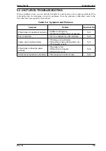
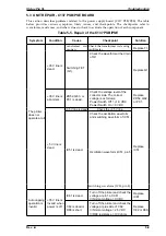
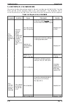


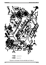
5.3 UNIT REPAIR - C137 PSB/PSE BOARD
This section describes problems related to the power supply board (C137 PSB/PSE). The table
below provides various symptoms, likely causes, and checkpoints. The checkpoints refer to
waveforms, resistances, and other values to check to evaluate the operation of each component.
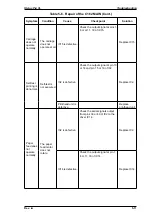
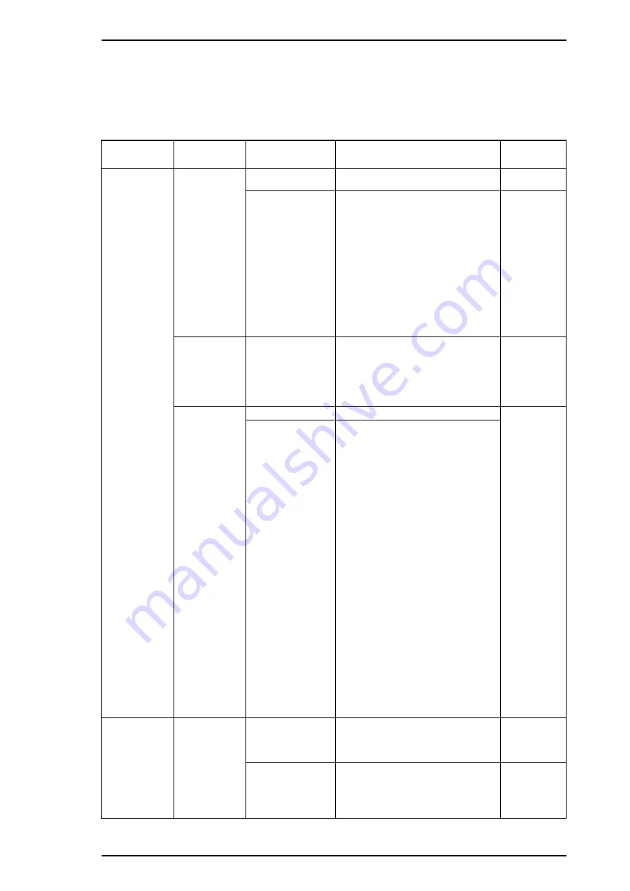
Table 5-5. Repair of the C137 PSB/PSE
Symptom
Condition
Cause
Checkpoint
Solution
The printer
does not
operate at all.
+35 V line is
dead.
Transformer coils
are open.
Check the transformer coils using a
multimeter.
Replace T1.
Switching FET
(Q1).
Check the waveform at the drain
of Q1.
Replace Q1.
+35 V line is
abnormal.
ZD52, Q83, or
PC1 is dead.
Check the voltage level of the
collector side. The correct
voltage is as follows:
Power Switch Off = +1.8 VDC
Power Switch On = 0 VDC
Replace
ZD52, Q82,
or PC1.
+5 V line is
dead.
+35 V line is dead.
Check the +35 V line.
Replace
IC51.
IC51 is dead.
Check the oscillation waveform
and switching waveform of IC51.
Oscillation waveform (IC51, pin 5)
Switching waveform (IC51, pin 8)
Auto capping
operation is
invalid.
+35 V line is
invalid when
power is off.
IC81 is dead.
Turn off the printer and check the
voltage at pin 1 of IC81.
❏
Normal voltage = 0 VDC
Replace
IC81.
C82 is dead or
R88 is short.
Turn off the printer and check the
voltage at plus side of C82.
❏
Normal voltage = 2.5 VDC
❏
R88 resistance = 100 ohms
Replace
C82 or R88.
Stylus Pro XL
Troubleshooting
Rev. -A
5-9
Summary of Contents for Stylus Pro XL
Page 1: ...EPSON COLOR INKJET PRINTER Stylus Pro XL SERVICE MANUAL EPSON 4004677 ...
Page 93: ...Rev A 5 i ...
Page 127: ...EPSON ...


