


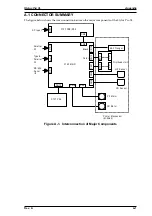
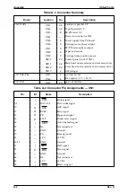


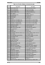

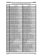
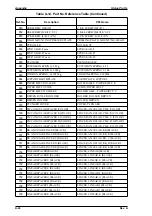

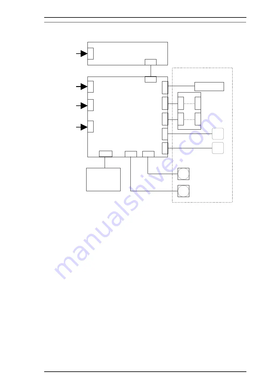
A.1 CONNECTOR SUMMARY
The figure below shows the interconnection between the major components of the Stylus Pro XL.
CN1
C N 2
C137 PSB/PSE
C1 3 7 PNL
C1 6 2 MAI N
CN1
C N 5
CN1
1
CN9
CN8
C N 7
C N 6
C N 1 0
CN2
CN1
CN
CN
2
CN3
C
N12
CN
CN1
3
AC I nput
Parallel
I/F
Type B
Parallel
I/F
RS -4 2 2
Serial
I/F
PF Mo t or
CR Mo t o r
ASF Plu ng er
Printhead Unit
HP S en so r
CR Se n so r
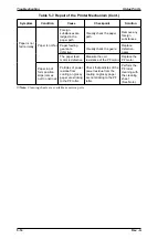
Printer Mechanism
(M-4 A6 0)
Co lo r
Black
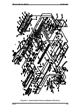
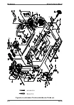
Figure A-1. Interconnection of Major Components
Stylus Pro XL
Appendix
Rev. A
A-1
Summary of Contents for Stylus Pro XL
Page 1: ...EPSON COLOR INKJET PRINTER Stylus Pro XL SERVICE MANUAL EPSON 4004677 ...
Page 93: ...Rev A 5 i ...
Page 127: ...EPSON ...


