
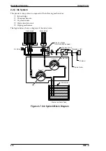
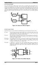
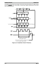
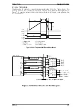


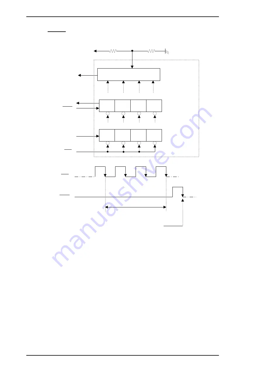
The following figure shows the contents of the four-bit serial data and how this data transacts
with the SLA7041MS driver. The step time of the reference voltage is determined by the interval
time of the
STROBE pulse.
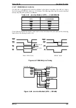
ST RB
C L K
SL A7 0 4 1 M S
1-b it
2-b it
3-b it
4-b it
Vref
+5 V
Vref
ST RB
C L K
a
b
c
1-b it
2-b it
3-b it
4-b it
a
b
c
Vref Voltage Selection
Circuit
To Mot or
(Phase Signa l)
Phase
Latch
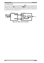
4-bit Serial Data
4-bit Shift Register
Phase
Reading of serial data from the
Phase signal in order
At this time, the reference voltage selection
circuit checks phase signal outputs
Figure 2-21. Serial Data Transfer Procedure
Operating Principles
Stylus Pro XL
2-18
REV.-A
Summary of Contents for Stylus Pro XL
Page 1: ...EPSON COLOR INKJET PRINTER Stylus Pro XL SERVICE MANUAL EPSON 4004677 ...
Page 93: ...Rev A 5 i ...
Page 127: ...EPSON ...


