


List of Figures
Figure 3-1. Disassembly Flowchart . . . . . . . . . . . . . . . . . . . . . . . . . . . . . . . . . . 3-2
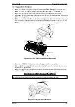
Figure 3-2. C137 PNL Control Panel Removal . . . . . . . . . . . . . . . . . . . . . . . . . 3-3
Figure 3-3. Upper Case Removal. . . . . . . . . . . . . . . . . . . . . . . . . . . . . . . . . . . . 3-3
Figure 3-4. Power Supply Unit Removal . . . . . . . . . . . . . . . . . . . . . . . . . . . . . . 3-4
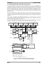
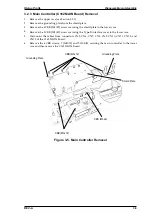
Figure 3-5. Main Controller Removal . . . . . . . . . . . . . . . . . . . . . . . . . . . . . . . . . 3-5
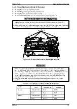
Figure 3-6. Printer Mechanism (M-4A60) Removal . . . . . . . . . . . . . . . . . . . . . . 3-7
Figure 3-7. Ink Cartridge Clamp Removal . . . . . . . . . . . . . . . . . . . . . . . . . . . . . 3-8
Figure 3-8. Ink Cartridge Holder removal . . . . . . . . . . . . . . . . . . . . . . . . . . . . . . 3-9
Figure 3-9. Printhead Removal . . . . . . . . . . . . . . . . . . . . . . . . . . . . . . . . . . . . . 3-9
Figure 3-10. Head Spacer Position . . . . . . . . . . . . . . . . . . . . . . . . . . . . . . . . . 3-11
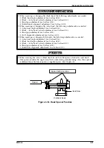
Figure 3-11. Front Frame Removal . . . . . . . . . . . . . . . . . . . . . . . . . . . . . . . . . 3-12
Figure 3-12. Carriage Unit Removal. . . . . . . . . . . . . . . . . . . . . . . . . . . . . . . . . 3-12
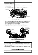
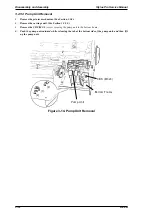
Figure 3-13. Pump Unit Removal . . . . . . . . . . . . . . . . . . . . . . . . . . . . . . . . . . . 3-13
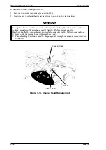
Figure 3-14. Cleaner Head Replacement . . . . . . . . . . . . . . . . . . . . . . . . . . . . 3-14
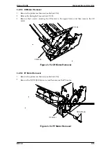
Figure 3-15. CR Motor Removal . . . . . . . . . . . . . . . . . . . . . . . . . . . . . . . . . . . 3-15
Figure 3-16. PF Motor Removal . . . . . . . . . . . . . . . . . . . . . . . . . . . . . . . . . . . . 3-15
Figure 3-17. HP Sensor Removal . . . . . . . . . . . . . . . . . . . . . . . . . . . . . . . . . . 3-16
Figure 3-18. PE Sensor Removal. . . . . . . . . . . . . . . . . . . . . . . . . . . . . . . . . . . 3-16
Figure 3-19. Tension Roller Assembly Removal . . . . . . . . . . . . . . . . . . . . . . . 3-17
Figure 3-20. Paper Feed Roller Assembly Removal . . . . . . . . . . . . . . . . . . . . 3-17
Figure 3-21. Upper Frame Removal. . . . . . . . . . . . . . . . . . . . . . . . . . . . . . . . . 3-18
Figure 3-22. Attaching the Torsion Spring . . . . . . . . . . . . . . . . . . . . . . . . . . . . 3-18
List of Tables
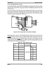
Table 3-1. Insert Location of the Block Resistor . . . . . . . . . . . . . . . . . . . . . . . . 3-7
Table 3-2. Insert Location of the Block Resistor . . . . . . . . . . . . . . . . . . . . . . . 3-10
3-ii
Rev.-A
Summary of Contents for Stylus Pro XL
Page 1: ...EPSON COLOR INKJET PRINTER Stylus Pro XL SERVICE MANUAL EPSON 4004677 ...
Page 93: ...Rev A 5 i ...
Page 127: ...EPSON ...


