
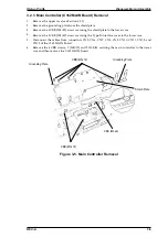


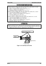
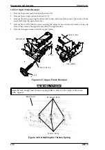


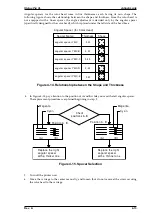
3.2.5.10 Upper Frame Removal
1.
Remove the printer mechanism (see Section 3.2.4).
2.
Remove the carriage unit (see Section 3.2.5.2).
3.
Remove the E-ring securing the knob shaft to the sub frame; then remove the knob with the
knob shaft from the right side frame.
4.
Remove the 5 CBN (M3
×
5) screws securing the upper frame to both side frames or the sub
frame. Then remove the upper frame with 4 PF support rollers.
5.
Remove the upper frame with 4 PF support rollers.
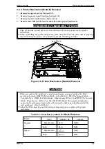
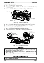
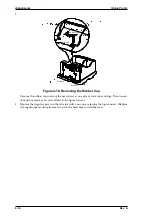
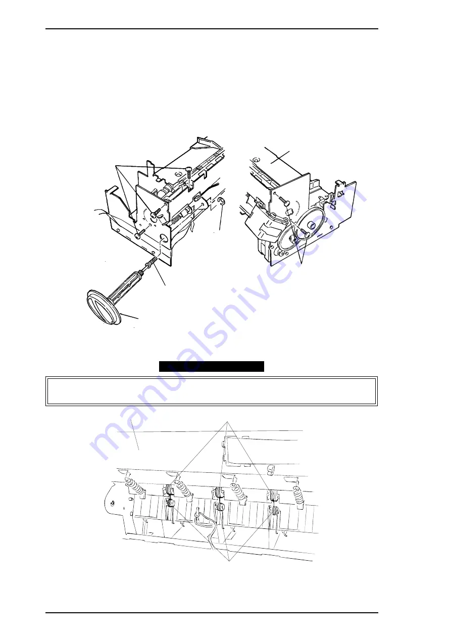
ASSEMBLY POINT
Assemble each straight end of torsion spring 6700s to attach to the center of the driven
roller support.
CBS (M3x5)
C BS (M3 x5 )
K n o b
Te nsion Spring
E-ring
U p p e r F ra m e
Figure 3-21. Upper Frame Removal
Base Frame
PF Suppor t Roller
Tension Spring
Figure 3-22. Attaching the Torsion Spring
Disassembly and Assembly
Stylus Pro XL
3-18
REV.-A
Summary of Contents for Stylus Pro XL
Page 1: ...EPSON COLOR INKJET PRINTER Stylus Pro XL SERVICE MANUAL EPSON 4004677 ...
Page 93: ...Rev A 5 i ...
Page 127: ...EPSON ...


