


8.
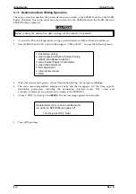
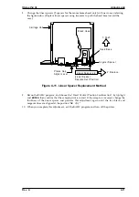
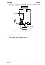
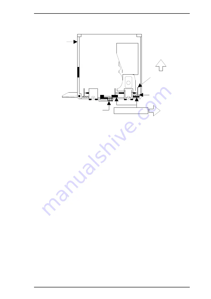
Change the linear spacers (2 spacers for the monochrome head only) with new ones, referring
the figure below. (Replace linear spacers using tweezers to push the head base toward the
rear.)
9.
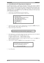
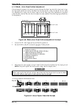
Rerun the BASIC program, and choose the “Head Vertical Position Confirmation” by typing
3
and
ENTER
; then confirm that the sample print is correct. If the sample is incorrect, change the
thickness of the linear spacer and perform this adjustment again until the two black and
magenta lines are aligned at the position “
OK (0)
.”
10. When you complete this adjustment, exit the BASIC program and turn off the printer.
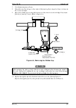
1: Push
Carriage Unit
Platen Gap
Adjust Lever
2: Replace
Black Head
He ad B as e
Linear Spacer x 2
(Linear Spacer
Rep lacement Position)
Angu lar Spacer
Figure 4-11. Linear Spacer Replacement Method
Stylus Pro XL
Adjustments
Rev. A
4-11
Summary of Contents for Stylus Pro XL
Page 1: ...EPSON COLOR INKJET PRINTER Stylus Pro XL SERVICE MANUAL EPSON 4004677 ...
Page 93: ...Rev A 5 i ...
Page 127: ...EPSON ...


