EPSON Stylus Pro 7000
Revision A
Disassembly & Assembly
Disassembly Flow
130
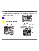
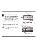
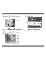
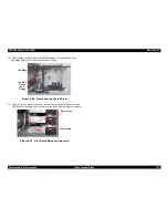
10. Repeat steps 7 through 9 for the B head.
4.2.3.4 Removing the CR Board Assembly
1.
Remove the R Side Cover as described in “R Side Cover Removal” on
page 113.
2.
Remove the L Side Cover as described in “L Side Cover Removal” on
page 115.
3.
Remove the I/C Holder Cover as described in “I/C Holder Cover Removal”
on page 115.
4.
Remove the H Top Cover as described in “H Top Cover Removal” on
page 116.
5.
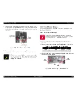
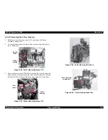
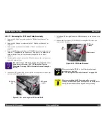
Remove and three screws (CPPM3x6)securing the CR board.
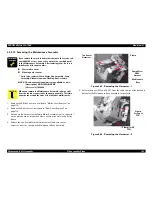
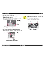
Figure 4-39. CR Board Guide Removal
6.
Remove one screw (CP(W)M3x6) securing the ground line, washer (M3),
and CR board guide.
7.
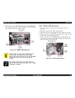
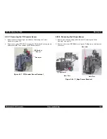
While holding down the CR Board (left edge), remove two FFC cables
from the FFC lock-type connectors.
Figure 4-40. CR Board FFC Removal
C H E C K
P O I N T
!
When replacing the printheads, fold the flat cable behind
the printhead and make sure the printhead snaps fully
into place. When properly installed, the printhead ID will
be directly behind and at the same height as the PG Cam
Shaft. If the PG Cam Shaft does not partially block the line
of sight of the printhead ID (when looking at the ID level/
from straight in front), the printhead is not installed
properly.
!
When attaching the dampers to the printhead, follow the
same order, left to right, as shown on the control panel:
K, C, M, LC, LM, Y.
You may find it helpful to manually release the Carriage Lock
by pushing down the cutter and move the carriage away from
the capping position.
CR board guide
Screw,
ground
line, and
washer
Three screws
FFC to Main Board
FFC to printheads
CR Board
Summary of Contents for StylusPRO 7000
Page 1: ...EPSONStylusPRO7000 Color Large Format Inkjet Printer SEIJ99017 SERVICE MANUAL ...
Page 6: ...Revision Status Revision Issued Date Description Rev A February 17 2000 First Release ...
Page 11: ...C H A P T E R 1 PRODUCTDESCRIPTION ...
Page 55: ...C H A P T E R 2 OPERATINGPRINCIPLES ...
Page 80: ...C H A P T E R 3 TROUBLESHOOTING ...
Page 106: ...C H A P T E R 4 DISASSEMBLY ASSEMBLY ...
Page 153: ...C H A P T E R 5 ADJUSTMENT ...
Page 195: ...C H A P T E R 6 MAINTENANCE SETUP ...
Page 199: ...C H A P T E R 7 APPENDIX ...
Page 223: ......
Page 224: ......
Page 225: ......


