EPSON Stylus Pro 7000
Revision A
Product Description
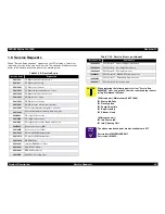
Service Requests
49
1.8 Service Requests
When “Service Req nnnnnnnn” appears on the LCD display, a fatal error
requiring a service technician has occurred. The nnnnnnnn indicates what
needs to be fixed to return the printer to a working state.
Table 1-39. Service Errors
Service Code
Explanation
0001000
PF Motor encoder check error
0001001
PF Motor out of step
00010002
PF Motor overcurrent
00010003
PF Motor in-position time-out error
00010004
CR Motor encoder check error
00010005
CR Motor out of step
00010006
CR Motor overcurrent
00010007
CR Motor in-position time-out error
00010008
Servo interrupt watchdog time-out error
00010009
System interrupt watchdog time-out error
0001000A
CR origin sensor error
0001000B
PF origin sensor error
0001000C
PG origin sensor error (Head slide error)
0001000D
Cover sensor error (00)
0001000E
Cover sensor error (01)
0001000F
CR motor PWM output error
00010010
PF motor PWM output error
00020000
NVRAM Error
00020001
Internal RAM Check Error
00020002
SRAM Check Error
00020003
DRAM Check Error
0002000B
Mail box receiving error
100000004
CPU Vector 4 - General illegal instruction
100000006
CPU Vector 6 - Slot illegal instruction
100000006
CPU Vector 9 - CPU address error
10000000A
CPU Vector 10 - DMAC\DTC address error
10000000B
CPU Vector 11 - Watchdog time-out error
1000000**
CPU Vector 32~63; wrong trap
C A U T I O N
When replacing the following parts to clear “Service Req.
00000100” error, you need to clear the corresponding counter
using “Maintenance Mode 2”.
[Affected parts] (Maintenance Kit SP7000)
!
Waste Ink Pads
!
Flushing Box
!
Pump Assembly
!
Cap Assembly
!
Cleaner, Head
[Affected counters]
!
Init. Waste Ink
!
Init. Cleaning Unit
C H E C K
P O I N T
The above mentioned parts are also available as a KIT.
Description: MAINTENANCE KIT
Parts code: 1054038
Table 1-39. Service Errors (continued)
Service Code
Explanation
Summary of Contents for StylusPRO 7000
Page 1: ...EPSONStylusPRO7000 Color Large Format Inkjet Printer SEIJ99017 SERVICE MANUAL ...
Page 6: ...Revision Status Revision Issued Date Description Rev A February 17 2000 First Release ...
Page 11: ...C H A P T E R 1 PRODUCTDESCRIPTION ...
Page 55: ...C H A P T E R 2 OPERATINGPRINCIPLES ...
Page 80: ...C H A P T E R 3 TROUBLESHOOTING ...
Page 106: ...C H A P T E R 4 DISASSEMBLY ASSEMBLY ...
Page 153: ...C H A P T E R 5 ADJUSTMENT ...
Page 195: ...C H A P T E R 6 MAINTENANCE SETUP ...
Page 199: ...C H A P T E R 7 APPENDIX ...
Page 223: ......
Page 224: ......
Page 225: ......


