background image

receipt, journal, slip printer

Operator's Manual

400208200

Summary of Contents for TM-930II Series

Page 1: ...receipt journal slip printer Operator s Manual 400208200 ...

Page 2: ...ates shall be liable to the purchaser of this product or third parties for damages losses costs or expenses incurred by purchaser or third parties as a result of accident misuse or abuse of this product or unauthorized modifications repairs or alterations to this product or excluding the U S failure to strictly comply with Seiko Epson Corporation s operating and maintenance instructions Seiko Epso...

Page 3: ...at his own expense WARNING The connection of a non shielded printer interface cable to this printer will in validate the FCC Verification of this device and may cause interference levels which exceed the limits established by the FCC for this equipment You are cautioned that changes or modifications not expressly approved by the party responsible for compliance could void your authority to operate...

Page 4: ...ce printing l Precision paper feeding at 1 144 inch l Maximum 2 K bytes receive buffer l The command protocol is based on the ESC POS standard l Either the serial interface RS 232C or RS 422 or the parallel interface Centronics is selectable as a factory option Before trying to use this printer be sure to read this manual carefully to make sure that you use the unit correctly The illustrations in ...

Page 5: ...ndixes contain information on general specifications character code tables and a list of commands CONTENTS Chapter 1 Unpacking the Printer 2 1 1 Checking the Contents of the Box 2 1 2 Choosing a Place for the Printer 3 1 3 Names and Functions Part 3 Chapter 2 Before Setting Up 5 2 1 Connecting the Power Supply to the Printer 5 2 2 Connecting the Host Computer to the Printer 6 Chapter 3 Installing ...

Page 6: ...r Corrections 34 5 5 Cover Open Function 34 5 6 Recovering from a Paper Jam 35 Chapter 6 software Control 37 6 1 Printer Control 37 6 2 Command Descriptions 38 6 3 Commands 38 APPENDIX 50 APPENDIX A General Specifications 58 APPENDIX B Connectors 63 APPENDIX C Interfaces 65 APPENDIX D Near End Detector Sat Handling 71 APPENDIX E Notes on Using the Drawer Kick out Connector 74 APPENDIX F Character ...

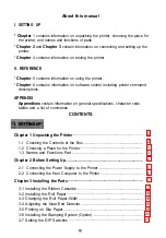
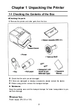
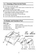
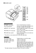
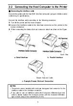
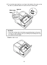
Page 7: ...I SETTlNG UP ...

Page 8: ... from the box Check that the units are not damaged If there are damaged or missing components please contact the dealer Before using printer remove the transport damper n Maintenance Keep the packing case and the transport damper for future transportation to pro tect from damage Optional Parts Power supply PS 120 or 130 2 ...

Page 9: ...printer Choose a location which is stable Intense vibration or shock may damage the printer n Ensure printer has enough space it can be used easily n Use the ribbon cassette specified n Do not use the printer without installing paper and a ribbon cassette 1 3 Names and Functions Part Part names Roll paper cover Ribbon cover Operation panel Interface connector Drawer kick out connector Power connec...

Page 10: ...inter is on line and turns off when it is off line The printer is in error status when the ON LINE lamp blinks ON LINE switch Toggles between on and off line status RECEIPT FEED switch Feeds the receipt paper JOURNAL FEED switch Feeds the journal paper RESET switch Sets the printer to the initial conditions the same as when the power is turned on This switch is located on the same side as the pane...

Page 11: ...rinter to the power supply make sure that the voltage 24 VDC and power specifications match the printer s require ments l Using an incorrect power supply can cause serious damage to the printer Connect the power unit according to the following procedure Confirm the power is turned off to the power unit then connect the power cable to the connector Turn on the power switch of the power unit CAUTION...

Page 12: ...or on the printer in the correct orientation When connecting the drawer kick out connector attach as shown in the Figure C Earth Wire a Serial Interface b Parallel Interface Drawer Kick out Cable c Example Drawer Kick out Connection NOTES l This printer comes installed with inch type hexagonal lock screws to fix the interface cable to the interface connector l If you plan to use an interface cable...

Page 13: ...ssette that matches the printer s specifications Turn on the printer and open the lower ribbon cover The print head will move to the home position left side Eliminate the slackness in the ribbon by turning the ribbon feed roller in the direction of the arrow Install the ribbon cassette from above and press it into position ...

Page 14: ...he ribbon is positioned between the head unit and the ribbon guide CAUTIONS l l Do not turn the feed roller in the direction opposite that shown by the arrow To remove a ribbon cassette pull it up by holding the protruding tab on top the cassette with your fingers Close the ribbon cover ...

Page 15: ...t ribbon cassette Turn on the power to the unit and open the ribbon cassette cover Confirm the head is in the home position then remove the ribbon cassette Install a new ribbon cassette refer to 3 1 Installing the Ribbon Cassette then close the ribbon cover 9 ...

Page 16: ...ing the Roll Paper Width Confirm that the edge of the roll paper is cut straight across and is not folded or crooked Good Bad Bad Turn on the printer The POWER lamp the RECEIPT OUT lamp and the JOURNAL OUT lamp will light Check if the ribbon cassette is already installed If not install the cassette first Open the roll paper cover 10 ...

Page 17: ...er in the correct orientation Right Wrong While leaving some slack in the roll paper insert the end of the roll paper straight into the paper inlet The roll paper will be automatically fed into the printer approximately 18 cm and the RECEIPT and the JOURNAL lamps will go off 11 ...

Page 18: ...the printer Press the JOURNAL FEED switch to feed the journal paper so that it can be would onto the take up shaft Insert the end of the journal paper into the groove on the take up roll and turn the shaft two or three times to secure the roll paper 12 ...

Page 19: ...he take up shaft into the printer and close the roll paper cover then turn the key to lock CAUTION l Eliminate the slackness in the journal paper by turning the take up shaft in the direction of the arrow see 13 ...

Page 20: ...ipt paper cover While pressing the tab marked PRESS on the release lever at the left side of the tear off unit remove the remaining roll paper by pulling it out in the direction of the arrow Install a new roll of receipt paper refer to 3 2 Installing the Roll Paper Close the receipt paper cover 14 ...

Page 21: ...sors or the like While pressing the tab marked PRESS on the release lever at the right side of the tear off re move the remaining roll paper by pulling it out in the direction of the arrow Install new roll paper refer to 3 2 Installing the Roll Paper Close the roll paper cover turn the key to lock the cover ...

Page 22: ...he power and open the roll paper cover remove the take up shaft cross head the roll paper and the paper edge guides Unscrew the outside screw of the roll paper holders at both sides with a screwdriver and remove the side roll bracket at both sides by pulling it up and away from you Left side Roll Bracket Bracket Install one edge of the side roll bracket at both sides into the slot and tighten down...

Page 23: ...lling the side roll bracket on the journal paper side after confirming the belt of the take up unit is installed in position Insert the paper edge guides at the side of each paper inlet until they click Paper edge Guides Remove the auxiliary shaft from the tip of the take up roll Set DIP switches SW2 3 through SW2 4 refer to 3 7 Setting the DIP Switches Table 3 Turn on the printer and install the ...

Page 24: ...tall the roll paper Close the roll paper cover 3 4 Adjusting the Near End Detectors n The Near End Detector When the roll paper is close to running out the near end detector causes the RECEIPT OUT lamp to light for the receipt paper and the JOURNAL OUT paper to light for the journal paper The amount of the remaining roll paper which causes near end status can be adjusted n Method of adjustment Adj...

Page 25: ...nkles especially along the top edge Use only flat sheets of paper If the sheet is wrinkled paper may jam Check once again that the roll paper and ribbon cassette are already installed in position If not install them first Turn on the printer The POWER lamp will light Use the software command to switch the printer to the slip paper print mode The printer will be in the paper setting wait status and...

Page 26: ... 3 6 Installing the Stamping System Option Installing the stamp system When you install the stamping system the printer can be set so the receipt paper is stamped in conjunction with printing Be sure to specify the correct model name when you purchase the unit See APPENDIX A General Specifications for the recommended stamp Open the receipt paper cover Remove the receipt paper Install the stamp sys...

Page 27: ...tables on the next page n Changing the DIP switches Follow these steps when changing DIP switch settings Turn off the printer Use a pointed article such as a pair of tweezers to change DIP switch settings Move a switch upward to set it to the ON position and downward to the OFF position Turn the printer back on NOTES l Change the DIP switch settings only after you have turned off the printer l Cha...

Page 28: ...Selects interface Always ON Selects international character set default Refer to Table 1 Parallel Interface Number SW1 1 SW1 2 SW1 3 SW1 4 SW1 5 SW1 6 SW1 7 SW1 8 Function ON OFF Auto line feed Always valid Depends on AUTO FEED XT signal Selects font 9 x 9 7 x 9 default ON LINE switch Enable Disable function default Selects interface Always OFF Selects international character set default Refer to ...

Page 29: ... ON OFF ON ON United Kingdom OFF OFF ON ON I Denmark I ON ON OFF ON I Sweden OFF ON OFF ON Italy ON OFF OFF ON Spain OFF OFF OFF ON I Japan ON ON ON OFF I Norway OFF ON ON OFF Denmark II ON OFF ON I OFF NOTE Any combination of switch settings other than those listed will auto matically default to the United States selection 23 ...

Page 30: ...nabled only with the parallel interface l The SLCT signal is disabled with the serial interface Receive Buffer Capacity Serial Interface Receive Buffer Capacity SW2 1 SW2 2 32 bytes 128 bytes 256 bytes 2048 bytes ON ON OFF ON ON OFF OFF OFF Parallel Interface Receive Buffer Capacity SW2 1 SW2 2 0 bytes 128 bytes 258 bytes 2048 bytes ON ON OFF ON ON OFF OFF OFF Roll Paper width Roll Paper Width SW2...

Page 31: ...tance SW3 10 Reception termina Connected tion resistance Open NOTE For the parallel interface DIP switch 3 is not provided Selects transmitting speed Transfer rate BPS Invalid SW3 4 SW3 4 SW3 6 ON ON ON 150 OFF ON ON 300 ON OFF ON 600 OFF OFF ON 1200 ON ON OFF 2400 OFF ON OFF Text ON OFF OFF Text OFF OFF O F F NOTES l For the parallel interface DIP switch 3 is not provided l SW3 9 and SW3 10 are e...

Page 32: ...wing steps Version 1 3 ESC FOS Serial Interface Baud rate 9600 tcs Check that the ribbon cassette and the roll paper are installed correctly Data bits 8 bits none Stop bit 1bit or more Turn on the printer while pressing Handshaking DIR DSR the RECEIPT FEED switch to per Buffer Capacity form the self printing on the roll 2048 bytes paper Turn on the printer while pressing the JOURNAL FEED switch to...

Page 33: ...II REFERENCE ...

Page 34: ...te none of the panel switches can be used ON LINE switch Release switch Paper Feed switch 1 ON LINE switch Function Switches between ON LINE and OFF LINE Note l Normally the printer is ON LINE and can print data When switched OFF LINE the printer stops after printing the current line l The ON LINE switch can be disabled by command ESC c 6 or DIP switch When disabled the ON LINE OFF LINE state cann...

Page 35: ...ed switch Function Feeds the journal paper based on the line feed parameters set by ESC 2 and ESC 3 when this switch is pushed once If the switch is held the printer executes continuous line feeding Note l When the ON LINE switch is enabled the journal feed switch can be used only when the printer is OFF LINE When the ON LINE switch is disabled the journal feed switch is always valid l Since the p...

Page 36: ...must be within the range indicated below 1 Roll Paper Units mm Paper width 58 mm All the numeric values are typical Receipt side Journal side Figure 5 2 Roll Paper Printable Area 2 Slip Paper Units mm All the numeric values are typical Figure 5 3 Slip Paper Printable Area 30 ...

Page 37: ...of the slip to the printing position is 8 7 mm A calculated value Printable area is 180 dots 360 positions from the right edge To print endorsements on the back in the specified area within 1 5 inches from the top set the check so that there is a 3 mm space at the bottom Units mm All the numeric values are typical Figure 5 4 Lengthwise Printing 4 Widthwise printing on the front Paper length is sma...

Page 38: ...rformed in the forward direction only 2 Since the paper feed pitch is inaccurate directly after the paper feed direction has been changed special attention should be paid to the printing thereafter 3 The mechanical structure allows the paper to feed only when the roll paper is loaded properly Accordingly roll paper must be loaded onto both the receipt and journal sides before selecting slip paper ...

Page 39: ... and length will affect paper feeding Therefore the user must check these specifications in advance refer to Figure 5 5 The user should also pay attention when the paper is very wide and the glued portion is located on the side the paper may not be feed properly Since the slip detector is equipped with a photo sensor paper that has one or more holes at the detector position or is translucent must ...

Page 40: ...hen the power is turned on or when the printer is reset using the reset switch The RAM check consists of writing and reading back the data pattern 55H AAH If a problem is detected the printer stops all operation thereafter and blinks the ON LINE LED 2 Recovery This error is fatal The printer cannot be recovered 5 5 Cover Open Function n Cover open function If the roll paper cover or the ribbon cov...

Page 41: ...e screw at the left side of the head cover and remove cover Head Cover Remove the jammed paper around the head the head NOTE l If you can remove the jam at this stage go to Turn the key to unlock the roll paper cover open the cover and remove the roll paper Push the lock lever of the tear off unit away from you lift up the tear off unit 3 5 ...

Page 42: ...off unit and return the lock lever to the forward position Insert the tab on the right side of the head cover into the slot and tighten down the head cover screw Close the roll paper cover and turn the key to lock the cover Close the ribbon cover 36 ...

Page 43: ...igures See APPENDIX D character code table There are two types of commands One byte commands l HT Horizontal tab l LF Print and line feed Several bytes commands l ESC SP Set character right side spacing l ESC 3 n Set line spacing to n l44 inches How to use this table Horizontal by vertical hex i e 4XA J H denotes Hexadecimal denotes Decimal Numbers Refer to APPENDIX D Page 0 International characte...

Page 44: ...tents of the should be repeated k times The allowable range for the codes Provides a description of the command function Included only when necessary The default values for the commands Related commands Example of using the commands 6 3 Commands LF Name Print and line feed Format 0A H or 10 10 Description Prints the data in the print buffer and performs one line feed based on the current line spac...

Page 45: ...ult l The eject direction of the slip sheet is forward only ESC c 0 ESC C CR Name Print and carriage return Format 0D H or 13 10 Description If automatic line feed is enabled this command has the same functions as LF When automatic line feed is disabled ex ecutes printing only and the paper is not fed l Sets the print starting position to the beginning of the line Reference L F RS Name Journal tab...

Page 46: ...follows Bit Function Value 0 1 0 Character font 9 x 9 font 7 x 9 font 1 Undefined I 2 Undefined 3 Undefined I 4 Double height Canceled set enlarged mode 5 Double width Canceled set enlarged mode 6 Undefined I I 7 Undefined I I I Note Default l When both double height mode and double width mode are set quadruple characters are printed l Since bi directional printing may cause printing position mis ...

Page 47: ...1 Therefore the number of dots in the horizontal direction is cal culated as n1 256 x n2 l If the bit image data input exceeds the number of dots to be printed on a line the excess data is ignored l d indicates the bit image data Set a corresponding bit to 1 to print a dot otherwise set it to 0 l The bit image modes selectable by m are as follows Number of Vertical Dots B 8 Horizontal Direction Do...

Page 48: ...O HEAD 6 O HEAD 7 O H E A D 8 O Bottom HEAD 9 O print data ESC 2 Name Set 1 6 inch line spacing Format 1B H 32 or 27 10 50 10 Description Sets the line spacing to 1 6 of an inch Notes l Sets the line spacing only for the sheet s selected using ESC c 1 Reference ESC c l ESC 3 n Name Set line spacing using minimum units Format 1B H 33 H n or 27 10 51 10 n Range 0 n 255 Description Sets the line spac...

Page 49: ...t 1B H 40 H or 27 10 64l 10 Description Clears the data in the print buffer and resets the printer mode the same state as when the power is turned on Notes l The DIP switches are not read again l The data in the receive buffer is not cleared l If this command is executed in slip mode the slip sheet is ejected and the switching from slip mode to 2 sheet mode is performed mechanically ESC C n Name S...

Page 50: ...s the paper n 144 inches in the reverse direction l The predetermined line spacing remains unchanged l Sets the print starting position to the beginning of the line l This command should not be executed continuously more than two times l If n is out of range the printer will print but the paper will not be fed l If the paper gets out of the slip detector during slip printing the printer will print...

Page 51: ...on Notes Default Set cancel uni directional printing 1B H 55 H n or 27 10 85 10 n 0 n 2 5 5 Bets or cancels uni directional printing l Only the lowest bit of n is valid When n 1 B unidirectional printing is set When n 0 B uni directional printing is can celed and the bi directional printing is set l When unidirectional printing is set the printer prints from left to right l When the user wants to ...

Page 52: ...e as other paper l When this command is input the printer executes the following If a slip sheet which was previously selected is canceled the sheet is ejected If a slip sheet which was previously selected is reselected no operation is executed Default If either receipt or journal was previously selected and then a slip sheet is selected the printer waits for a slip sheet to be loaded n 3 ESC c1 n...

Page 53: ...ce ESC 2 ESC 3 ESC c 3 n Name Select paper detectors to output signals Format Range 1B H 63 H 33 H n or 27 10 99 10 51 10 n 0 n 255 Description Selects the paper detectors to output signals on the paper end status line l Each bit of n is used as follows 47 ...

Page 54: ... Therefore there will be a time lag between receiving this com mand and switching the paper end signal according to the condition of the receive buffer Reference n 3 ESC c 4 n Name Select paper detectors to stop printing Format 1B H 63 H 34 H n or 27 10 99 10 52 10 n Range 0 n 2 5 5 Description Selects the paper detectors used to stop printing l Each bit of n is used a follows Value Bit Function 0...

Page 55: ...nother slip sheet to be loaded In addition the detector checks for paper end after the print and paper feed sequence is completed Therefore if the actual paper length does not correspond to the paper feed length set by command the printer may continue printing even after the paper reaches its end The user should pay attention to this Default n 0 ESC c 5 n Name Enable disable panel switches Format ...

Page 56: ...the normal mode is fixed ON LINE but the receipt feed switch and journal feed switch are always valid n 0 or 1 depending on the DIP switch setting ESC d n Name Print and feed paper n lines Format 1B H 64 H n or 27 10 100 10 n Range 0 n 2 5 5 Description Prints the data in the print buffer and performs n line feeds l Bets the print starting position to the beginning of the line Default Not defined ...

Page 57: ...f m n Name Set cut sheet waiting time Format 1B H 66 H m n or 27 10 102 10 m n Range 0 m 1 5 0 n 6 4 Description Sets the time the printer waits for a slip sheet to be loaded and the time from when the slip sheet is loaded to when the printer starts operation l m specific the slip sheet waiting time to m x 1 minutes If no slip sheet is loaded after this time period has elapsed the sIip sheet mode ...

Page 58: ...ine l Valid only when receipt is selected for printing by ESC c 0 ESC o Name Stamp Format 1B H 6F H or 27 10 111 10 Description Executes stamping the receipt paper Notes l Valid only when input at the beginning of a line l Valid only when receipt is selected for printing by ESC c 0 ESC p m nl n2 Name Generate pulse Format 1B H 70 H m n1 n2 or 27 10 112 10 m n1 n2 Range m 0 0 n1 255 0 n2 255 Descri...

Page 59: ...is command is valid when the serial interface is selected When the parallel interface is selected this command is ig nored l The status to be transmitted is shown in the table below l When the connector is not used the value of bit 0 is always 1 l When DTR DSR control is selected the printer transmits only 1 byte after confirming that the host is ready to receive data DSR signal is SPACE If the ho...

Page 60: ...be ignored l The status to be transmitted is shown in the table below l When DTR DSR control is selected the printer transmits only 1 byte after confirming that the host is ready to receive data DSR signal is SPACE If the host computer is not ready to receive data DSR signal is MARK the printer will keep waiting until the host is ready When XON XOFF control is selected the printer transmits only 1...

Page 61: ... or cancels parallel printing printing the same data on the receipt journal sheets l Only the lowest bit of n is valid When n 1 B parallel printing is set When n 0 B parallel printing is canceled l Valid only when input at the beginning of a line l Valid only when both receipt and journal are selected as the print sheets by ESC c 0 n n 0 ESC c O 55 ...

Page 62: ...cter printing is set GS ENQ Paper feed direction Name Status enquiry Format 1D H 05 H or 29 10 5 10 Description Transmits the printer status when receiving this command Notes l This command is valid only when DTR DSR control is selected for the serial interface When the parallel interface is used or when XON XOFF control is selected for the serial interface this command will be ignored l The statu...

Page 63: ...ted before the n n will be pro cessed as 1D H Becomes 1 in the OFF LINE state due to a paper out cover open or ON LINE switch operation Therefore when this bit is 1 but paper is present the cover is closed and no mechanical error has occurred the printer can be set ON LINE by operating the ON LINE switch Becomes 1 when a mechanical error occurs related to auto cutting or detecting the home positio...

Page 64: ...5 Katakana 64 Hiragana 64 Double width Kanji 112 Extended graphics 128 International characters 32 Character structure 9 x 9 3 dot spacing in half dot unit 7 x 9 2 dot spacing in half dot unit The spacing can be set larger than the above values by command Character size Refer to Table A l Table A l Characters Per Inch Characters Per Second Characters Per Line character Size NOTES l Concerning the ...

Page 65: ...Refer to Figure A 1 Units mm Figure A l Ribbon Cassette Overall Dimensions 4 Stamp Recommended stamp FUJI COPIAN CPS 2038C Recommended ink FUJI COPIAN Super Ink purple Printable area dimension 38 mm width X 20 mm height Stamp overall dimensions Refer to Figures A 2 NOTE Stamp and stamp set should be supplied by the user Units mm Figure A 2 TM 930II 930IIP Stamp Overall Dimensions 59 ...

Page 66: ...The paper is automatically taken up by the journal paper feed motor Paper width According to the roll paper used a sub take up shaft can be installed or removed 8 Paper Paper feed method Paper feed pitch Paper feed speed Paper size Friction feed Default l 6 inch Can be set in units of 1 144 inch by software command Approx 64 3 ms line 1 6 inch feeding Approx 3 4 inches second continuous feeding Ro...

Page 67: ...4 to 0 07 mm l Total thickness of copy paper 0 09 to 0 25 mm NOTE Copy capability is greatly influenced by the ambient temperature so the user should be aware of this 9 Receive Buffer When the serial interface is selected buffer size 32 128 256 or 2048 bytes is selectable using DIP switches When the parallel interface is selected buffer size 0 128 256 or 2048 bytes is selectable using DIP switches...

Page 68: ... 100 million characters mean 2 dots wire per character 10 Environmental Conditions Temperature Operating Storage Humidity Operating Storage 5 to 40 C 10 to 50 C except for ribbon 30 to 85 non condensing 30 to 90 non condensing except for ribbon 11 External Dimensions and Weight Height 197 mm Width 251 mm Depth 298 mm Weight Approx 6 kg 12 Case Color EPSON standard gray 62 ...

Page 69: ...ternal Appearance 2 interface connectors Refer to APPENDIX C Interfaces 3 Power supply connector This connector is used to connect an external power source 1 Pin assignment Refer to Table B l 2 Model printer side Hosiden TCS7960 53 2010 or equivalent user side Hosiden TCP8927 63 1100 or equivalent Table B l Power Supply Connector Pin Assignment 63 ...

Page 70: ...2 Drawer kick out Connector Pin Assignments Pin Number Signal Name Direction 1 Frame GND 2 Drawer kick out drive signal Output 3 Drawer open close signal Input 4 24 VDC 5 NC 6 Signal GND 3 Drawer kick out drive signal output Output voltage Approx 24 VDC Output current 1 A or less Output waveform Outputs the waveform in Figure B 3 to the point A in Figure B 4 n7 ON time and n2 OFF time are specifie...

Page 71: ...e Drawer Kick out Connector APPENDIX C Interfaces 1 Serial interface RS 232C serial interface 1 Specification based on RS 232C Data transmission Serial Synchronization Asynchronous Handshaking DTR DSR or XON XOFF control selectable using DIP switch Signal levels MARK 3 to 15 V Logic 1 SPACE 3 to 15 V Logic 0 Stop bits 1 or more Connector printer side HONDA GMM A25HUGDFDB1 DB 25 or equivalent 65 ...

Page 72: ...ACE indicates that the printer can receive data and MARK indicates that the printer cannot receive data The signal turns to MARK in the following cases l During the period from when the power is turned on to when the printer initialization completes l During the self test printing l In the OFF LINE state l In the receive buffer full state l In a mechanical error state When XON OFF control is selec...

Page 73: ...rror has occurred NOTES l The XON code is 11 H and XOFF code is 13 H l In case of c XON is not transmitted when the receive buffer is full l In case of e XOFF is not transmitted when the receive buffer is full RS 232C setial interface 1 Specifications Data transmission Serial Synchronization Asynchronous Handshaking XON XOFF control Stop bits 1 or more Termination resistance Connected or open by D...

Page 74: ...rface 1 Specifications Data transmission 8 bit parallel Synchronization STROBE pulse supplied by host computer Handshaking ACKNLG and BUSY Logic level All of the interface control signals are TTL compatible Connector printer side HONDA ADS B36BLFDR116 or equivalent 68 ...

Page 75: ... feed are performed automatically by CR commend 15 NC 16 GND Signal ground 17 CHASSIS GND Chassis ground 18 NC 19 to 30 GND Signal ground 31 lNIT Input Printer hardware reset signal Normally this signal is HIGH The printer is reinitialized just as when power is turned on by receiving a LOW pulse of 50µs or more 32 ERROR Output This signal indicates whether the printer is in an error state or not I...

Page 76: ...t to this printer after confirming that ACKNLG is active or when BUSY is LOW l The interface cable should be as short as possible 3 Timing chart 4 Data control Reception of data is controlled by the ACKNLG or BUSY signal The BUSY signal goes HIGH depending on whether the receive buffer is available or not as follows a When the receive buffer capacity is 0 byte l During the period from when power i...

Page 77: ...ENDIX D Near End Detector Set Handling Adjusting roll paper near end The remaining detectable amount of roll paper differs depending on the inside and outside diameters of the paper core Therefore the minimum detectable amount corresponding to the paper core can be set as follows The inside diameter 0d of the roll paper used should be 10 mm or more 1 Measure the paper core thickness A 2 Match the ...

Page 78: ... between core Thickness and Adjustment Scale Position NOTES l To avoid detection errors due to the near end detector datection accuracy obtain the adjustment scale that corresponds to the paper pore thickness remaining paper thickness 2 mm l Be sure not to set the indicator part to the position 0 7 mm or fess lower than 1 to prevent the detecting lever malfunctions l Honeycomb shaped pore should n...

Page 79: ...d above is used l If there is an end mark at the end of the roll paper the end mark can act as an adhesive and the roll paper is pulled up In this case the remaining amount of paper does not apply to the figure above n Example of roll paper remaining amount adjustment The adjusting method and he remaining length of roll paper when the paper core that meets the JIS standard 0d 12 mm A 3 mm is used ...

Page 80: ... close solenoid load shall be 24 or more or the output current shall be 1 A or less 3 l Be sure to use the drawer kick out connector pin 4 24 V power output to drive the device Never connect any other power supply to the drawer kick out connector 4 In this case the peak current is 1 A and the energizing conditions described in 2 must be followed NOTES l Operation of this printer with incorrectly i...

Page 81: ...t meet formulas E l and E 2 cannot be used 3 Notes on using the drawers that do not satisfy the conditions described in 2 When the values of n1 and n2 are determined according to the conditions described in 2 the setting value range of n1 is 0 to 255 and the n1 value range inevitably becomes 0 n1 63 and the maximum ON time is 126 ms If the drawer needs more than 126 ms ON time set the ON time and ...

Page 82: ...0MS ON time 200 ms 300 ms wait routine NOTE RETURN OFF time 500 ms NOTE This part is indicated in Formula E 3 Set this value so that it can sat isfy Formula E 3 or provides an internal processing time at least as long as the wait routine time When the drawer is driven according to the conditions above the drive wave form is as shown in Figure E 2 Figure E 2 Example Drawer Drive Signal Waveform 76 ...

Page 83: ......

Page 84: ......

Page 85: ...Page 2 International character set U S A is selected 79 ...

Page 86: ......

Page 87: ...n International character set Country ASCII code hexadecimal 23 24 40 5B 5C 5D 5E 60 7B 7C 7D 7E 0 U S A 1 France 2 Germany 3 U K 4 Denmark I 5 Sweden 6 Italy 7 Spain 8 Japan 9 Norway 10 Denmark II 81 ...

Page 88: ...ed paper using minimum units 44 ESC K n Print and reverse feed using minimum units 44 ESC R n Select international character set 45 ESC U n Set cancel uni directional printing 45 ESC c 0 n Select print sheet s 46 ESC c 1 n Select sheet s for setting the line spacing 46 ESC c 3 n Select paper detectors to output signals 47 ESC c 4 n Select paper detectors to stop printing 46 ESC c 5 n Enable disabl...

Page 89: ... 52 ESC t n Select character code table 53 ESC u Transmit peripheral device status 53 ESC v Transmit printer status 54 ESC z n Set cancel parallel printing for receipt journal 55 ESC n Set cancel upside down character printing 56 GS ENQ Status enquiry 56 63 ...

Reviews: