Rev.B
Overview of Electric Circuits Appendix F-1
TM-L90 Service Manual
Confidential
Appendix F
Overview of Electric Circuits
General Description
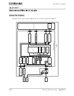
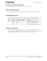
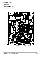
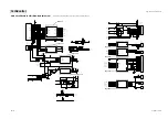
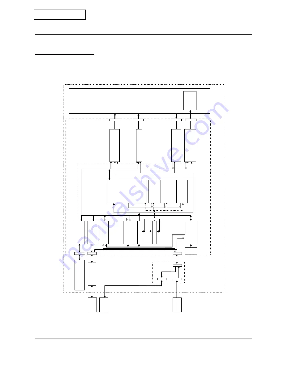
The figure below shows a block diagram of the electric circuits for the TM-L90.
Switch board
(with DIP s
w
itch)
I/F circuit board
Po
w
e
r
s
w
itch
P
o
w
ercontrol
circuit
V
olatile RAM
(U8)
DRAM
F
ont R
O
M
(U9)
Flash EEPR
OM
Prog
ra
m R
O
M
(U7)
Flash EEPR
OM
CPU
(U4)
BU
S
VI0
VB
US
P
aper f
eed motor dr
iv
e
circuit
A
uto cutter motor
dr
iv
e circuit
Sensor circuits
Ther
mal head dr
iv
e circuit
Ther
mal head
Pr
inter mechanism
VI0
+5V po
w
er system
+3.3V po
w
er system
+24V po
w
er system
DKD dr
iv
er
I/F circuit board
interf
ace
Switch board
interf
ace
Host
interf
ace
Dr
a
w
er
P
o
w
e
r supply
CN7
CN6
CN4
CNS3
CNS1
CNS2
CN11,12,13
CN10
CN8
CN9
Main circuit board unit
TM-L90
+24V
Sub board

