Rev.C
Disassembly and Assembly 3-7
TM-L90 Service Manual
Confidential
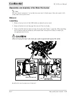
Follow the steps below to assemble the parts.
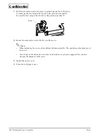
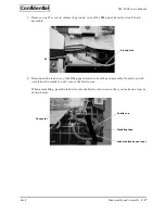
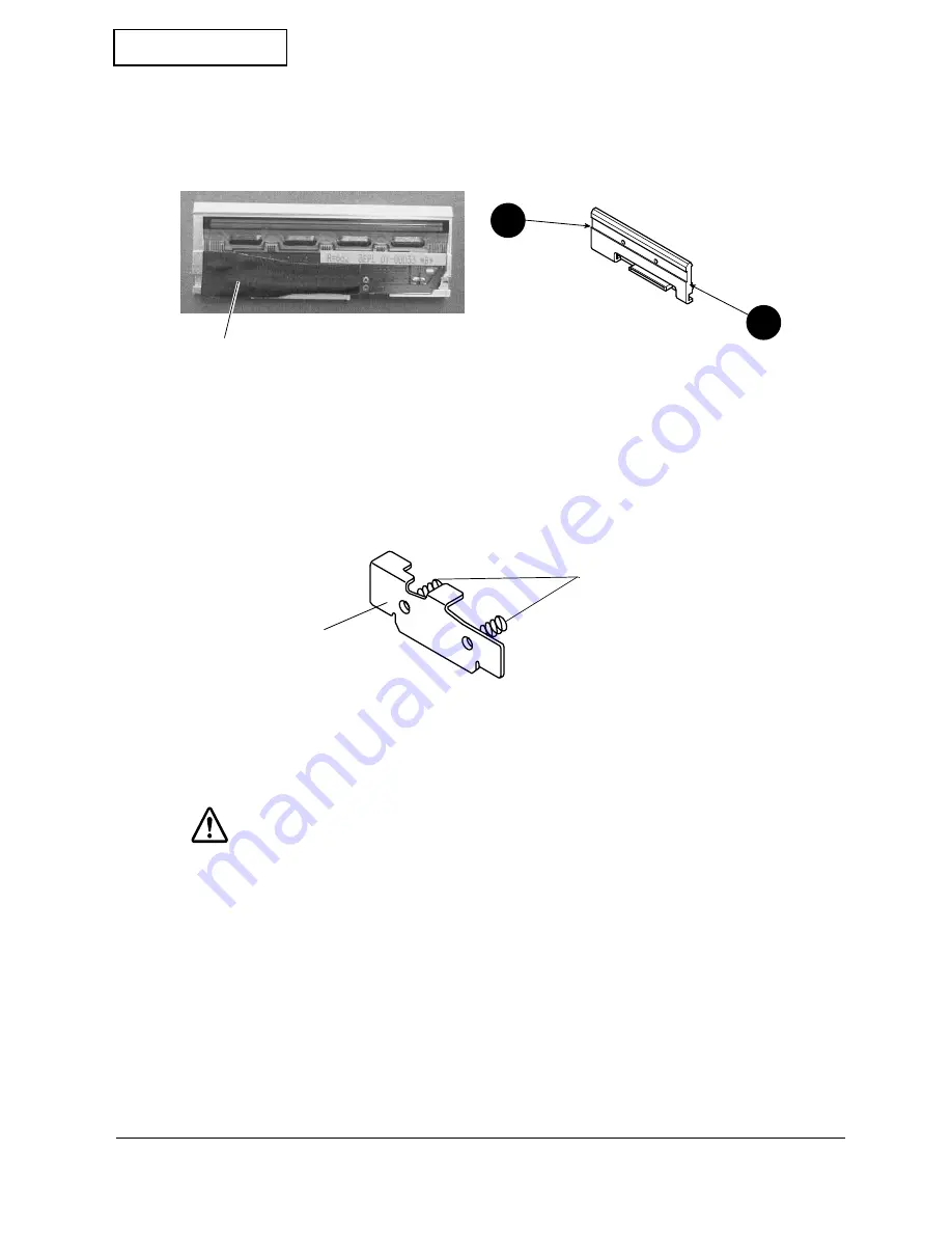
1. Attach the insulating tape on the new thermal print head assembly, as shown below; then
lubricate with G-45 along the surfaces on both ends of the head assembly.
2. Attach the head FFC to the connector of the thermal print head assembly.
3. Place the thermal print head assembly in its installation position inside the printer.
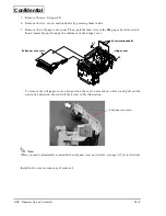
4. Insert the two head holder springs onto the two dowels on the spring holder plate by
rotating them.
5. Insert the two head holder springs into the groove in the thermal print head assembly.
6. While holding the two head holder springs so they do not fly out, install the spring holder
plate.
CAUTION:
Be sure to hold the two head holder springs while installing the spring holder plate.
Otherwise, the head holder springs may suddenly fly out, creating the danger of
eye injury.
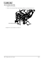
7. Adjust the two head holder springs so they are perpendicular with the thermal print head
assembly.
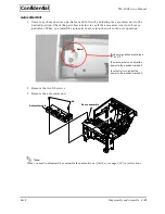
8. Attach the autocutter unit in its installation position. At this time, align the two dowels on
the frame assembly with the two slits in the autocutter unit.
Insulating tape
G-45
G-45
Head holder springs
Spring holder plate


