Rev.C
Disassembly and Assembly 3-13
TM-L90 Service Manual
Confidential
Main Circuit Board Unit
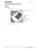
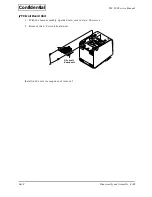
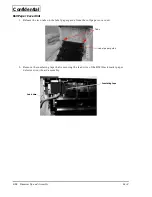
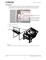
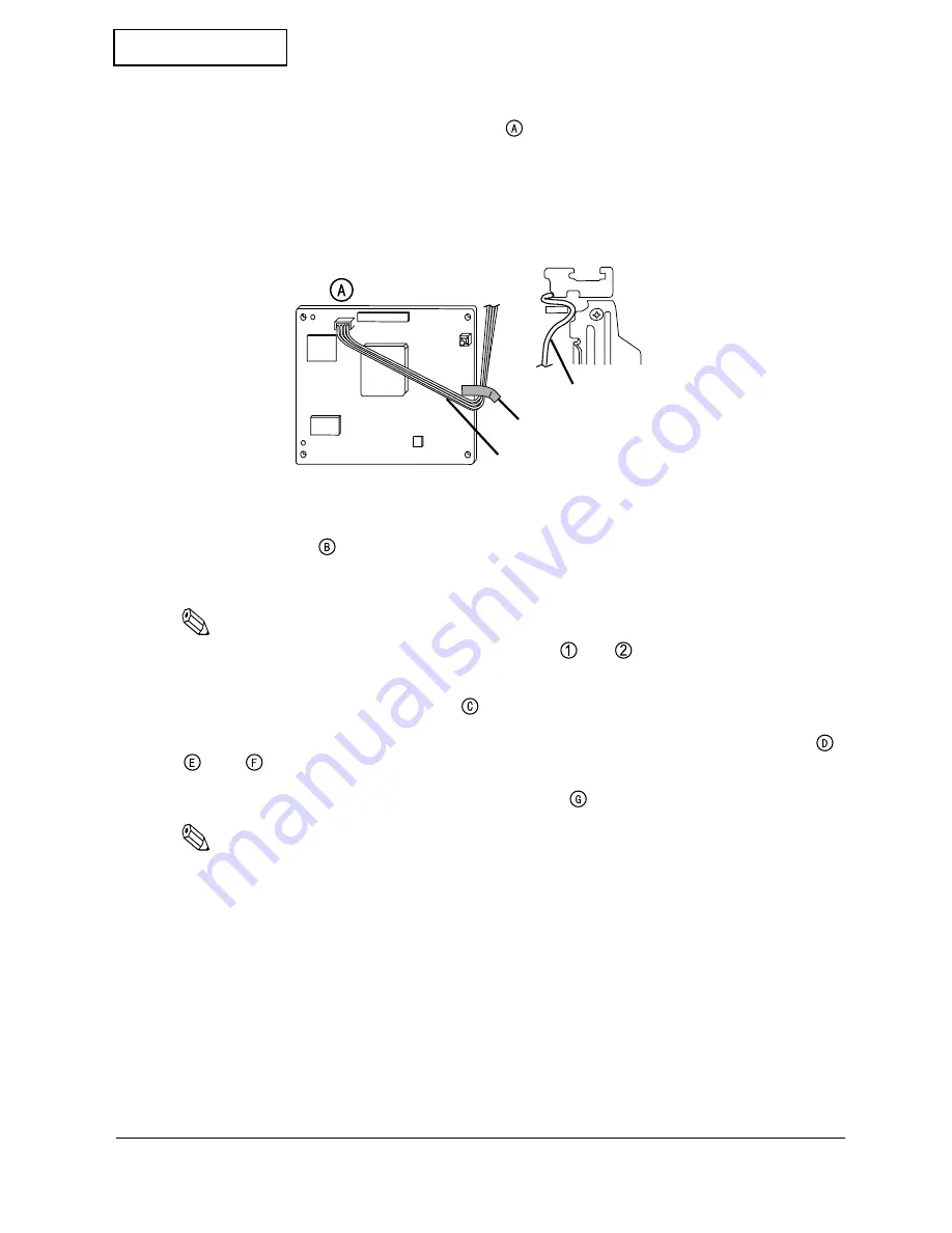
1. Remove the cutter lead wire from connector
. Then, remove the insulating tape securing
the lead wire.
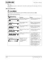
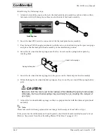
When installing, route the cutter lead wire as shown below, and then fix with the insulating
tape.
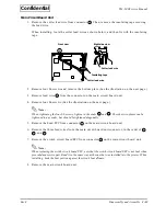
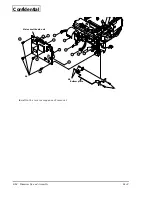
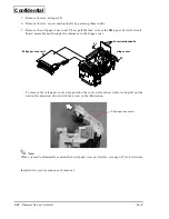
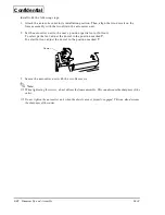
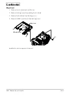
2. Remove four S6 screws and remove the bottom plate. (See the illustration on the next page.)
3. Remove lead wire
from the connector on the main circuit board unit.
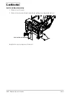
4. Remove four S6 screws. (See the illustration on the next page.)
Note:
When tightening the four S6 screws, tighten in the order
and
. The other two places can be
tightened in any order, but should be tightened diagonally.
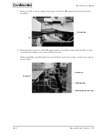
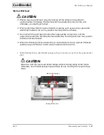
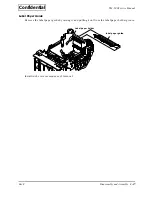
5. Remove the head FFC from connector
on the main circuit board unit.
6. Remove the three lead wires from the main circuit board unit connector, in the order of
,
, and
.
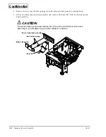
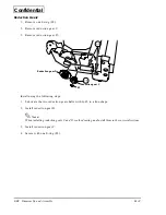
7. Remove the switch circuit board FFC from connector
on the main circuit board unit.
Note:
When replacing the switch circuit board FFC, note that the switch circuit board FFC is not bent when
provided as a service part. Bend it in the same way as the one that was installed into the printer. When
installing, hook the bent portion against the circuit board frame.
8. Remove the main circuit board unit.
Right side view
Front view
Cutter lead wire
Cutter lead wire
Insulating tape

