background image

4-22

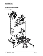
   Disassembly and Assembly

Rev. B

Confidential

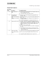
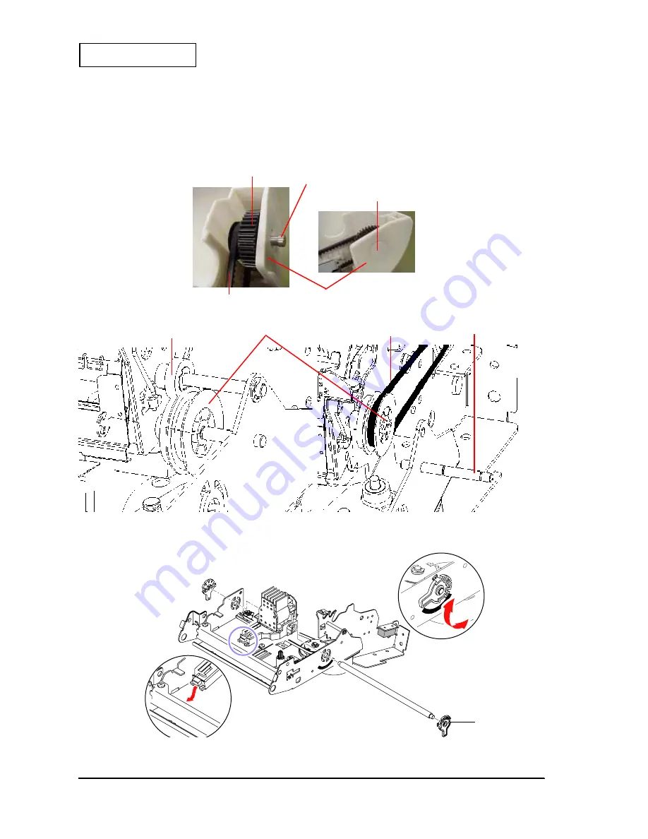
Attaching the Take-up Belt

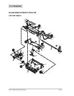
Removing the Adjustment Roller Shaft Holder

Take-up transmission gear (1105)

Take-up belt (523)

Take-up transmission shaft (1112)

Middle take-up gear (1106)

Hook the take-up belt (523) to the take-up transmission gear (1105). 

Install the back case (130) onto the mechanism assembly. After that, install the take-up 
belt (523) and paper take-up gear assembly (131) onto the back case.
Put the back case sheet over the hole in the back case.

Take-up gear shaft (139)

Paper take-up gear  assembly (131)

Back case (130)

Paper take-up gear assembly (1110)

Take-up belt (523)

Adjustment roller 
shaft holder

When removing the shaft holder adjustment 
roller, you need to rotate it as following.

Summary of Contents for TM-U220 Series

Page 1: ...Confidential Service manual TM U220 Series Type A English 404619501 Rev B Issued date Issued by EPSON ...

Page 2: ...he information in the document You may not reproduce store or transmit the confidential information in any form or by any means electronic mechanical photocopying recording or otherwise without the prior written permission of Seiko Epson Your obligations under this Agreement are in addition to any other legal obligations Seiko Epson does not waive any right under this Agreement by failing to exerc...

Page 3: ... of Repair 2 1 Repair Flow 2 1 Confirming the User s Environment 2 1 Confirming the Printer Status 2 1 Self test 2 2 Service Utility 2 5 Chapter 3 Troubleshooting Preparations for Troubleshooting 3 1 Before Servicing 3 2 Diagnosing Failures 3 2 Symptoms and Solutions 3 3 Symptoms when Power is On 3 3 Symptoms when the All Function Test is Executed 3 15 Symptoms for other operations 3 20 Test Point...

Page 4: ...6 Lubrication Reference 4 28 Chapter 5 Adjustment and Setting Setting the Installation Position for the Roll Paper Near End Detector 5 1 Adjusting the Detection Point for the Roll Paper Near End Detector 5 2 Setting the Paper Roll Width 5 3 Setting the Autocutter 5 4 Platen Gap Adjustment 5 5 Carriage Belt Tension Adjustment 5 6 Adjust Various Settings 5 7 How to Confirm the Current Settings 5 7 A...

Page 5: ...dded 4 3 4 4 Illustration was changed 4 5 4 16 4 17 An explanation of the roll paper cover assembly was added 4 6 4 7 Cutter rotation plate 1129 added 4 7 Step 6 added to disassembly 4 10 4 11 4 20 Paper feed roller plate B deleted 4 11 An explanation of the platen assembly 1 was added 4 30 An explanation of the lubrication reference was added Chapter 6 Inserting roll paper and installing or repla...

Page 6: ...level of importance as defined below Read the following carefully before handling the product WARNING You must follow warnings carefully to avoid serious bodily injury CAUTION Observe cautions to avoid minor injury to yourself damage to your equipment or loss of data Note Notes have important information and useful tips on the operation of your equipment ...

Page 7: ...it Tampering with this product may result in injury fire or electric shock Be sure to use the specified power source Connection to an improper power source may cause fire or shock Never insert or disconnect the power plug with wet hands Doing so may result in severe shock CAUTION Parts on the circuit board may become hot during operation Therefore wait approximately 10 minutes after turning the po...

Page 8: ... Describes the instructions to complete repair of the product Chapter 3 Troubleshooting Provides information on troubleshooting Chapter 4 Disassembly and Assembly Describes disassembly and assembly procedures Also shows exploded diagrams and lubrication point diagrams for this product Chapter 5 Adjustments and Settings Describes adjusting and settings procedures Chapter 6 Preparation for shipment ...

Page 9: ...h is packed with the alphanumeric model cannot be used with the multilingual model Be sure to use the PS 180 with the multilingual model If the AC adapter C power supply is connected to the multilingual model by mistake the printer may not operate correctly For example printing may stop before all lines are printed or the printer might print the same line repeatedly Type A Type B Type D Two color ...

Page 10: ...ard Paper width selections 76 69 5 or 57 5 mm 3 2 74 or 2 26 Be sure to change the paper guide spacer if paper of a different width is used Then set the customized value in printer memory for the correct paper width For details about how to set the paper width see Chapter 6 Installation Power supply unit types Exclusive external power supply for the alphanumeric model AC Adapter C North America on...

Page 11: ...by using this button when a paper out is detected Power Switch and Power Switch Cover The power switch is on the front of the printer Press this switch to turn on the printer Power Switch Cover This cover prevents the power from being turned off accidentally during printing If you need to turn the power on or off while the cover is attached you can insert a small screwdriver or similar tool into o...

Page 12: ...hat meets the specifications Be sure not to touch the manual cutter Otherwise you may cut your fingers 1 Using scissors cut the leading edge of the roll paper 2 Turn on the printer and open the roll paper cover by using the tab 3 Open the unit by using the unit open lever as shown below Unit open lever ...

Page 13: ...that the top and bottom sheets are aligned at the paper exit Do not allow paper to be loaded as shown below 5 If you are not using the take up flange pull out a small amount of roll paper and close the roll paper cover Then tear off the paper with the manual cutter You can skip steps 6 through 11 6 When using 2 ply roll paper pull out the roll paper to the bottom front of the printer as shown belo...

Page 14: ...e sure that the paper is aligned with the flange as shown 10 Feed the paper with the FEED button so that the paper is taken up by the flange 11 Close the roll paper cover and tear off the roll paper with the manual cutter as shown below Note Do not open the roll paper cover during printing or paper feeding When using the printer be sure to cut the roll paper with the manual cutter after paper feed...

Page 15: ...sed ribbon follow the steps below 1 Unpack the ribbon cassette and turn the knob in the direction shown to take up any slack 2 Open the printer s ribbon cassette cover using the tabs on each side of the cover 3 Remove the old ribbon if there is one 4 Insert cassette as shown below Put ribbon between print head and platen Push cassette down until it clicks Note Make sure the ribbon is installed bet...

Page 16: ...Right margin 5 8 mm 57 5 mm paper Width 47 5 mm 150 dots x 300 positions Left margin 4 2 mm Right margin 5 8 mm Space from autocut to print start Space from manual cut to print start 36 mm Type A B 26 mm Type C D 28 mm 27 mm 20 2 mm 27 mm Type D 22 1 mm Type A B 34 9 mm Receive buffer Alphanumeric 1KB 40 bytes Multilingual 512 bytes 40 bytes Alphanumeric 1KB 40 bytes Multilingual 512 bytes 40 byte...

Page 17: ...mal state follow the instructions in the chapter to troubleshoot based on the symptom Repair Flow Confirming the User s Environment Confirm the printer s settings by using the service utility Confirming the Printer Status Confirm the status of the printer you are repairing Confirm that the power turns on off run the self test run all function tests with the service utility and check other items fo...

Page 18: ...Power LED light comes on Mechanical initializing operation occurs ERROR LED light is off POWER LED does not light See page 3 3 ERROR LED light See page 3 3 ERROR LED flashes See page 3 4 PAPER OUT LED lights See page 3 6 Run the self test Refer to page 2 2 for operation POWER LED light comes on Prints the printer status See page 2 3 Prints the roll pattern after the FEED button is pressed See page...

Page 19: ...r capacity is 4KB Does not print when the receive buffer capacity is 40 bytes Busy condition 3 3 Differs depending on DIP SW1 8 Resident character 4 4 Performs a multilingual CG judgment when printing resident characters 7 Paper roll width 5 5 Differs depending on the paper roll width set with the memory switch customized value Dot spacing between characters 6 6 Differs depending on DIP SW2 1 9 Ch...

Page 20: ...air Guide Rev B Confidential Roll Pattern Normal print result Explanation Paper feeds 2 lines Paper is fed to a position where the user can see the ending message at left Black 6 lines Red 6 lines Red 6 lines ...

Page 21: ...M U220 Type A model printer 2 Communication condition selection Select the I F used with the printer You can confirm the communication conditions set for the printer by running the self test Refer to the self test section for details 3 Communication test 4 Confirm the communication status with the connected printer Normally the following message appears When the communication conditions are set co...

Page 22: ...printing This outputs a test pattern to confirm printer status Follow the screen instructions to operate Confirmation of the drawer operation You can confirm the drawer open function and the change in the open close status Follow the screen instructions to operate Setting for notification of power on You can enable or disable the notification function for power on Firmware update You can update th...

Page 23: ...mory memory switches communication conditions and customized value Receipt print function Prints patterns to confirm print operations and print quality Roll paper cut function The Type A model autocutter cuts roll paper after each printing on the roll Drawer open close function Runs a test of drawer open close operation while printing the receipt pattern Be sure to connect the drawer kick to the p...

Page 24: ... displayed When the sensor is not installed depending on the printer model you can skip with the Skip button Test results are OK when the tests confirm the normal operation of the sensors 3 Click If you want to skip the test 1 Indicate the sensor to test 2 Follow the message to operate the printer ...

Page 25: ...int result Explanation Prints execution date Prints execution time Prints EPSON Prints TM U220 Prints product serial number 1 Prints graphic pattern Checks for missing dots See Dots are missing continuously on page 3 12 Prints ANK characters 2 Performs full cut 3 Note 1 When the serial number is not registered on the product itself NG is printed 2 When using the 2 color ribbon prints in 2 colors 3...

Page 26: ...oduct serial number 1 Prints setting status of memory switches 2 Prints setting status of customize value 3 Performs partial cut 4 Note 1 When the serial number is not registered on the product itself NG is printed 2 3 When the default setting is changed is printed before the memory switch number 4 When autocutter setting is full cut partial cut is not performed ...

Page 27: ...ng on specifications Prints defined bit image data in NV memory 1 Prints defined data in NV user memory 2 Prints information on EPSON NV memory It is changeable with the printer status 3 Prints definition of command default values Note 1 2 Data defined by a user must be backed up and restored Main program version is printed Boot program version is printed Original program version is printed Manufa...

Page 28: ...er prints a pattern using the built in character set 4 The self test automatically ends and cuts the paper after printing the following completed 5 The printer is ready to receive data as soon as it completes the self test Note If you want to pause the self test manually press the FEED button Press the FEED button again to continue the self test Normal print result Explanation Prints execution dat...

Page 29: ...en the roll paper cover using the tab as shown in the below illustration 3 Remove the jammed paper Note If you turn the power off accidentally during printing the cutter blade may stop in the paper feed path So paper may not be fed normally at first when you turn the power on again If the cutter blade does not return to the normal position the autocutter unit may be jammed If so follow the procedu...

Page 30: ...escribed above to return the cutter to its normal position Before Servicing Pages iv to v at the beginning of this manual provide precautions you should observe to perform work safely and supply the necessary information to service this product safely Always read that information before starting your work Diagnosing Failures Use one of the following methods to identify the area where a failure occ...

Page 31: ...e sub circuit board unit 123 Completed if the POWER LED lights Main circuit board unit 201 Refer to page 3 21 Check the resistance value of fuses F1 and F4 Make sure neither fuse is blown If the circuit board has no damage such as burns replace fuse F1 or F4 Completed if the POWER LED lights If the fuse blows when power is turned on unplug all connectors from the mechanism assembly 120 and check a...

Page 32: ...of the HP board assembly 518 Make sure the signal changes when you block the sensor Replace the HP board assembly 518 Completed if operation is normal Check the connection of main circuit board unit 201 connectors Make sure they are plugged in securely CN7 carriage motor sub assembly 1034 CN4 HP board assembly 518 Plug in the connectors securely Completed if operation is normal Check if the parts ...

Page 33: ...drop Completed if operation is normal Check connection of the head FFC 521 Make sure it is plugged into the print head unit 503 and connector CN9 on the main circuit board unit 201 Connect the head FFC 521 Completed if operation is normal Check the continuity of the print head unit 503 Make sure wires are not broken or shorted out Connect the print head unit 503 Completed if operation is normal Ch...

Page 34: ...problem Roll paper Check the roll paper Make sure it is loaded correctly Make sure enough paper is left Replace the roll paper Completed if the PAPER OUT LED turns off Paper end assembly 514 Check operation of the paper end assembly 514 Make sure the continuity changes when you operate the switch Replace the paper end assembly 514 Completed if the PAPER OUT LED turns off Near end sensor Check oper...

Page 35: ...it is loaded correctly Load roll paper that meets specifications Completed if operation is normal Paper jam Check the paper path Make sure there is no paper jam Open the roll paper cover assembly and remove any jammed paper Completed if operation is normal Gear does not rotate Check the gear operation Make sure the following gears rotate Paper feed gear 1063 Paper feed middle gear B 510 Paper feed...

Page 36: ...ted out Replace the PF lead wire set 1047 Completed if operation is normal Paper feed motor sub assembly 1046 Check the resistance value Make sure it is 7 2 Ω or less Replace the paper feed motor sub assembly 1046 Completed if operation is normal Main circuit board unit 201 Check if the parts have any damage Make sure the following parts look normal Connector CN8 U8 Replace the main circuit board ...

Page 37: ...he print is correct Table 3 8 ERROR during Printing Probable part probable cause Checkpoints Action to correct the problem Autocutter AC error Check the connection of the main circuit board unit 201 connector Make sure the AC lead wire set 1090 is connected Plug in the connector Completed if operation is normal Check the operation of the drive gear sub assembly 1072 Make sure it rotates with rotat...

Page 38: ...1 Completed if operation is normal Roll paper cover open error Check the state of the cover when the error occurs Be sure not to open the roll paper cover during printing If MSW 8 8 is OFF close the roll paper cover again Completed if operation is normal If the MSW 8 8 is ON turn power on again Completed if operation is normal If the error occurs when the roll paper cover is not open refer to Cann...

Page 39: ...mpleted if cutting is normal Check the movable cutter blade on the cutter frame assembly 114 Make sure it does not have any nicks Replace the cutter frame assembly 114 Completed if cutting is normal Table 3 10 Ribbon Feed Mechanism not Functioning Correctly Probable part probable cause Checkpoints Action to correct the problem Ribbon cassette Check the mounting Make sure it is installed correctly ...

Page 40: ...fective gear Completed if the operation is normal Adjustment roller shaft holders 506 Check the platen gap adjustment 0 45 mm falls with no weight applied 0 55 mm does not fall Adjust the platen gap refer to page 5 5 Completed if printing is normal Table 3 12 Dark Print Probable part probable cause Checkpoints Action to correct the problem Adjustment roller shaft holders 506 Check the platen gap a...

Page 41: ...ted if operation is normal Paper hold spring 1014 Check the spring mounting Make sure it is mounted correctly Refer to page 4 18 Insert the paper hold spring 1014 correctly Completed if operation is normal Paper hold roller 1015 Check operation Make sure it rotates smoothly Replace the paper hold roller 1015 Completed if operation is normal Paper guide roller 1045 Check operation Make sure it rota...

Page 42: ...acter Check the resident character set Make sure it is same as the character set used by the customer Update the firmware Completed if printing is normal Check if this error message is printed ERROR If so the multilingual font is not correct Please download the correct one Make sure the message above is not printed Update the firmware Completed if printing is normal If printing is not normal repla...

Page 43: ...holder plate 508 Check for defects Make sure you see no defects such as deformation Replace the roll paper holder plate 508 Completed if operation is normal Table 3 18 Noisy Printing Probable part probable cause Checkpoints Action for the problem Roll paper is inserted incorrectly Check the roll paper Make sure it meets specifications and is loaded correctly Load roll paper that meets specificatio...

Page 44: ...t the correct communication settings Completed if operation is normal I F cable Check the I F cable connection Make sure the I F cable is plugged in securely Plug in the I F cable correctly Completed if operation is normal Check the continuity with a tester Make sure no wires are cut or shorted out Be sure the cable is wired correctly Replace the I F cable Completed if operation is normal I F circ...

Page 45: ... again using the printer status function Completed if printing is normal Memory switch setting Check the memory switch setting Make sure it is the same as the setting used by customer If you do not know the customer s setting make sure it is in the factory default state Refer to page 5 10 Set again using the printer status function Completed if printing is normal Table 3 21 Drawer 1 or 2 not Kicke...

Page 46: ...er rotates smoothly Replace the NE detector holder or lever Completed if the test passes Main circuit board unit 201 Check the parts for defects Make sure connectors CNC2 and CN6 are connected Replace the main circuit board unit Completed if the test passes Table 3 23 Test for the RE Sensor Fails Probable part probable cause Checkpoints Action to correct the problem HP board assembly 518 Check the...

Page 47: ...r Be sure wires are not cut or shorted out Be sure wires are arranged correctly Replace the cover open assembly Completed if the test passes Main circuit board unit 201 Check the parts for defects Make sure connector CN4 is connected Replace the main circuit board unit Completed if the test passes Table 3 25 Paper FEED Button Test Fails Probable part probable cause Checkpoints Action to correct th...

Page 48: ...lt is located in the correct position Confirm that the take up belt 523 is attached correctly Completed if the belt is driven correctly Table 3 28 Opening and Closing the Ribbon Cover is not Smooth Probable part probable cause Checkpoints Action to correct the problem Ribbon cover 109 Confirm the condition of 2 projections on the cover Make sure neither is broken Replace the ribbon cover 109 Compl...

Page 49: ...ply U9 pin 5 3 3 V Logic circuit power supply GND Bottom assembly frame 0 V Mechanism power supply Autocutter 117 power supply F3 24 V Print head power supply Q7 pins 5 or 6 or 7 or 8 24 V Roll paper cover open sensor 515 power supply Cover opened CN4 pin 5 3 3 V Cover closed 0 V HP sensor 518 power supply On home position CN4 pin 2 0 V Not on home position 3 3 V NE sensor 1096 power supply Suffic...

Page 50: ...tor 1034 4 phase stepping motor Head carriage drive Remove the cable connector connected to CN7 on the main circuit board Test between pin 1 and pin 3 and between pin 2 and pin 4 Approx 7 2 Ω per 1 phase Receipt paper feed motor 1046 4 phase stepping motor Receipt paper feed Remove the cable connector connected to CN8 on the main circuit board Test between pin 1 and pin 3 and between pin 2 and pin...

Page 51: ...ability and a lubricant s low temperature characteristics require special attention EPSON has conducted thorough analyses of the technical data and wide ranging experimentation on different lubricants The EPSON selection of lubricants prescribed for use with the printer is based on the results of such research The prescribed EPSON lubricants are available in 40 cc 40 gr metal cans or plastic conta...

Page 52: ...reful not to subject the circuit boards to shock or vibration because this may damage them Do not touch the circuit board or cable terminals with your hands to prevent contamination that may result in a malfunction Hold circuit boards only by their edges Always remove the power supply unit from the printer before working Power is flowing to the internal circuit boards even if you turn the printer ...

Page 53: ...wing this diagram as well as the explanations for the target item How to use the key map 1 Find the component enclosed in a box with solid black lines not dotted lines that you want to remove 2 Trace the line upward from that component to START 3 You need to remove all components or units in the path back to START Note that the steps for disconnecting cables and removing plates on the units are no...

Page 54: ...agram 128 W01 S02 119 106 S02 127 113 S13 S13 F S02 1092 S03 A B C E F D 122 S03 S03 S03 102 129 130 139 1110 S03 139 131 135 136 1111 136 1084 109 110 111 126 S03 120 1085 123 S01 S01 S01 S01 S01 201 S03 S03 S03 S03 112 112 1004 1095 S01 S01 107 523 108 134 127 1099 S02 B A 107 S02 S03 ...

Page 55: ...ck case 130 Remove the paper take up gear assembly 1110 When attaching the paper take up gear assembly 1110 be sure that the take up gear shaft 139 is attached from the correct direction I F circuit board unit 122 Remove the I F circuit board unit 122 Bottom plate 1004 Remove 4 screws S03 and remove the bottom plate 1004 Main circuit board unit 201 Remove connectors attached to the main circuit bo...

Page 56: ...embly Exploded diagram 1108 1010 1038 G 137 1125 E01 S11 S11 1005 E01 S07 S07 1013 1047 S11 S11 1046 515 S11 502 1018 S11 S11 S05 E03 1009 S05 E02 S05 1119 1105 1011 1112 1049 E02 E02 1050 1006 S05 S08 W02 1106 S05 C 523 138 S15 S02 S02 E04 E04 E01 1093 139 1110 131 1104 1114 1129 ...

Page 57: ...ort frame 1108 Remove 2 screws S02 and remove the cutter support frame 1108 6 Lubricate the cutter support frame 1108 with G 15 Fixed blade holder assembly 1013 Remove 2 screws S11 and remove the fixed blade holder assembly 1013 Roll paper guide unit 1038 Remove 2 screws S05 and remove the roll paper guide 1038 Roll paper holder 1010 Remove 2 screws and remove the back case 130 Remove 2 screws S08...

Page 58: ...Rev B Confidential Disassembling the Carriage Unit Exploded diagram 520 519 1022 1089 521 S06 503 1025 1081 S14 S12 507 E02 1029 1086 E01 E02 517 512 505 516 S11 518 506 1011 1128 1026 1097 1030 E03 1128 1034 S09 S09 506 1027 G E D ...

Page 59: ...ed to adjust the unit s platen gap See page 5 5 Note for attaching the carriage belt 507 See page 4 23 When you reattach the carriage belt adjust its tension See page 5 6 Confirm the head FFC 521 is connected correctly See page 4 23 6 Lubricate the carriage sub assembly 1025 with O 13 6 Lubricate the belt tension plate sub assembly 1086 with G 36 Carriage guide plate 1030 Carriage guide plate sub ...

Page 60: ...0 Disassembly and Assembly Rev B Confidential Disassembling the Rotation Frame Unit Exploded diagram 524 1061 510 1055 E01 1056 S09 1058 E01 509 1057 1053 1054 E01 504 S10 S10 1125 S09 140 S10 S10 S09 E01 ...

Page 61: ... feed middle gear B 510 6 Lubricate the gear plate D sub assembly 1057 with G 15 Platen assembly 3 522 Remove 1 E ring 3 E01 and pull out the platen shaft 1054 In doing so remove the paper feed middle gear B 510 the platen release plate 1055 and the platen release lever 504 together Take care not to lose the platen release spring 1056 Remove platen assembly 3 522 Remove 1 screw S09 and remove the ...

Page 62: ...4 12 Disassembly and Assembly Rev B Confidential Disassembling the Roll Paper Guide Roll Paper Holder Exploded diagram 514 1040 1041 1101 1039 1042 1096 1043 1126 D G 1045 1010 1038 508 S08 S08 ...

Page 63: ... the paper end assembly 514 you need to pull out the wire attached on the HP circuit board See page 4 24 Roll paper holder 1010 Remove 2 screws S05 and remove the roll paper holder plate 508 Remove the roll paper holder 1010 Reassembly steps Part names Assembly procedures NE lead wire set 1096 Remove the NE lead wire set 1096 Paper end assembly 514 Remove the paper end assembly 514 Roll paper guid...

Page 64: ... Disassembly and Assembly Rev B Confidential Disassembling the Autocutter Unit Fixed Blade Holder Assembly Exploded diagram 1102 104 1071 S04 115 1090 118 117 103 105 121 114 513 1016 1017 1127 1015 1014 F ...

Page 65: ...ew 105 and remove the micro switch 121 Remove 2 guard tubes C 118 When removing a guard tube C 118 you need to pull out the wire attached to the motor See page 4 19 6 Lubricate the paper hold roller 1015 with G 36 Reassembly steps Part names Assembly procedures Fixed blade 513 Remove the fixed blade 513 Remove the fixed blade spring 1016 Remove the fixed blade holder 1017 When you replace the pape...

Page 66: ...Roll Paper Cover Assembly Removing and Attaching the Top Case 1 Push the shaft and take it out from the inside of the frame 2 Remove 1 screw 3 Release the hooks in 3 positions as shown 4 Remove 2 screws Open lever shaft 1001 When removing the top case release both hooks as shown at right Case Hooks ...

Page 67: ...moving and Attaching the Top Case Continued Removing and Attaching Rotation Spring R Lift the case to remove as shown at right When removing the springs push the springs to the inside to release each hook as shown When attaching the springs insert each hook in the hole as shown Hook ...

Page 68: ...r Assembly and Manual Cutter Holder Attaching the Cover Open Assembly Place the paper hold spring on the fixed blade holder as shown Fixed blade holder assembly Spring Hook Hole Cover open assembly When attaching the cover open assembly to the frame be sure that the wires are threaded through the hole Hole Wires ...

Page 69: ...ng the Autocutter Unit Wires Be sure there is slack in the cable as shown Guard tube and lead wires Guard tube and lead wires Autocutter unit cable This is the point for attaching the top case hook When attaching the top case be sure not to catch the autocutter unit cable at this point ...

Page 70: ...otation frame 2 Platen rotation plate 2 Confirm that the edge of platen rotation plate 2 does not touch the edge of platen rotation frame 2 The point not to touch is marked with red in the illustration Platen release plate Insulator plate assembly When attaching the platen release spring you need to put it on the plate as shown ...

Page 71: ...0 S09 E01 1 Attach platen assembly 3 522 to the platen frame 1053 with 2 screws S09 from upper of the platen rotation frame 2 1125 2 Attach platen assembly 3 522 to the platen frame 1053 with 2 screws S10 from left side of the platen rotation frame 2 1125 3 Attach platen assembly 3 522 to the platen frame 1053 with 2 screws S10 from right side of the platen rotation frame 2 1125 ...

Page 72: ... up transmission gear 1105 Install the back case 130 onto the mechanism assembly After that install the take up belt 523 and paper take up gear assembly 131 onto the back case Put the back case sheet over the hole in the back case Take up gear shaft 139 Paper take up gear assembly 131 Back case 130 Paper take up gear assembly 1110 Take up belt 523 Adjustment roller shaft holder When removing the s...

Page 73: ... Assembly 4 23 TM U220 Type A Service Manual Confidential Attaching the Carriage Belt Attaching the Head FFC Carriage belt Carriage sub assembly When attaching the FFC to the frame be sure that the FFC is threaded as shown ...

Page 74: ...the carriage sub assembly is attached to the carriage guide plate as shown When removing the adjustment roller shaft holder rotate it as shown When attaching the HP board assembly be sure the wires are threaded through the hole and the board is attached to the hooks as shown HP board assembly Hook Hole RED GRY BLK BLU ORG WHT WHT When replacing the HP board assembly be sure the wires are soldered ...

Page 75: ...Rev B Disassembly and Assembly 4 25 TM U220 Type A Service Manual Confidential Attaching the Roll Paper Guide Unit Wires Roll paper guide unit ...

Page 76: ...g Placement for Each Cable The illustration below indicates paths for the cable wiring Wires in the PF lead wire set 1047 Cover open assembly wires 515 Wires in the NE lead wire set 1096 HP board assembly wires 518 Paper feed motor sub assembly wires 1046 ...

Page 77: ...4 Connecting the cable for the HP board assembly 518 CN6 Connecting the cable for the NE lead wire set 1096 CN7 Connecting the cable for the carriage motor sub assembly 1034 CN8 Connecting the cable for the PF lead wire set 1047 FFC When connecting the cables to the main circuit board be sure there is slack in the lead wires as shown Wires Wires CN10 Connecting the cable from CNC3 ...

Page 78: ...ication Some lubrication points are indicated in the illustrations below See the first few pages of this chapter for additional information about lubrication and also see the oil drop icons beside text passages in the disassembly procedure tables for various printer components ...

Page 79: ...int on the carriage sub assembly with G 36 Lubricate one point on the carriage guide plate with G 36 Carriage guide plate Carriage sub assembly Lubricate the point of contact between the rotation shaft and base frame with G 36 Lubricate the switching points on the carriage guide plate sub assembly ribbon switch lever with G 36 Carriage guide plate sub assembly Rotation shaft Base frame Carriage su...

Page 80: ...ng 3 E01 NE detector lever Oil G 36 Oil the joint of the paper feed reduction gear 2 and the paper feed reduction shaft 2 Oil G 36 Paper feed reduction gear 2 E ring 3 E01 Paper feed reduction shaft 2 Oil the joint of the middle take up gear and platen fixing shaft R Oil the joint of the take up transmission gear and the take up transmission shaft Take up transmission gear Oil G 36 Oil G 36 ...

Page 81: ...ll paper near end detector using the following steps 1 Loosen the detector adjustment screw with a coin or similar tool Turn the screw at least 3 or 4 times 2 Push the detector lever in until it touches the back of the hole 3 While pushing the detector lever turn the tab until the lever clicks into place in the desired hole 4 Secure the detector adjustment screw 5 Make sure the detector lever move...

Page 82: ...re To adjust the amount of remaining paper before the sensor detects a near end 1 Open the roll paper cover and remove the paper roll 2 Loosen the detector adjustment screw with a coin or similar tool 3 Adjust the detector by sliding the lever in either of the directions shown below 4 Tighten the detector adjustment screw 5 Check to be sure that the detecting lever moves freely 6 Replace the paper...

Page 83: ...Service Utility See page 2 5 Use the Memory Switch Setup Mode See page 5 12 For printer models with a paper near end detector be careful not to pinch the near end detector lead wires between the roll paper spacer and the roll paper holder and be sure to push the lead wires inside so that the paper end detector lead wires do not contact the motor gear 1 Open the paper roll cover 2 To set the each r...

Page 84: ...n the roll paper cover and remove it See page 4 16 3 Loosen the screw as indicated in following figure 4 Lift the top of the cutter unit upward towards you and remove from the dowel 5 When you select partial cut default you have to adjust the dowel to the right as shown When you select full cut you have to adjust the dowel to left as shown 6 Tighten the 2 screws Attach the roll paper cover again a...

Page 85: ...nt head unit to the left insert the gauge from the left side and adjust the gap while rotating the adjustment shaft holder 4 Move the print head unit to the right insert the gauge from the right side and adjust the gap while rotating the adjustment shaft holder 5 Move the print head unit to the left insert the gauge from the left side and check the gap If it does not meet the standard adjust the g...

Page 86: ... assembly adjust the tension properly and tighten with the screw 2 Check the belt tension Note Make sure the belt tension plate is stable when loosening the screw that you tightened for the belt tension plate while pulling the carriage belt with the tension gauge by 7 35N 3 Tighten the belt tension plate assembly again with the screw Hook the end of the tension gauge and adjust the tension Tension...

Page 87: ... 19200 bps you have to adjust the serial interface selection DIP switch and the serial communication condition memory switch When you adjust these items we recommend that you confirm whether the new setting is enabled or disabled Confirming by performing a self test See page 2 2 How to Confirm the Current Settings Use a self test to confirm the current settings See page 2 2 Adjusting the DIP Switc...

Page 88: ...DTR DSR 3 Reserved Fixed to Off 4 Word length 7 bits 8 bits 4 Serial interface selection Memory switch DIP switch 5 Parity check Yes No 5 Reserved Fixed to Off 6 Parity selection Even Odd 6 Reserved Fixed to Off 7 Transmission speed 4800 bps 9600 bps 7 Pin 6 reset signal Used Not used 8 Busy condition Receive buffer full Receive buffer full or offline 8 Pin 25 reset signal Used Not used Parallel U...

Page 89: ...ection Even Odd 6 Reserved Fixed to Off 7 Transmission speed 4800 bps 9600 bps 7 Reserved Fixed to Off 8 Busy condition Receive buffer full Receive buffer full or offline 8 Serial interface selection Memory switch DIP switch Parallel USB Ethernet Model Not for Serial Models DIP Switch 1 DIP Switch 2 SW Function On Off SW Function On Off 1 Auto line feed Enabled Disabled 1 Print column selection 42...

Page 90: ... Memory switch settings are stored in NV memory Therefore even if the printer is turned off the settings are maintained Excessive use of this function may destroy the NV memory As a guideline do not use this function more than 10 times a day Note MSW 2 3 Setting memory switch MSW 2 3 affects Simplified Chinese models only Memory Switch 2 SW Function On Off 1 Reserved Fixed to Off 2 Reserved Fixed ...

Page 91: ...om the printer every time the roll paper cover is opened MSW 8 5 and 8 8 can be set using the memory switch setup mode See page 5 12 Note These values can be set using the memory switch setup mode See page 5 12 Also when adjusting the roll paper width see page 5 3 Note There are 2 methods for changing serial communication conditions hardware DIP switches and software memory switches set using the ...

Page 92: ...ing the paper FEED button 3 Press the FEED button twice while the POWER ERROR and PAPER OUT LEDs are lighting 4 Close the cover The printer prints the current settings for the memory switches and instructions 5 Follow the printed instructions to set the switches Note During memory switch setup the PAPER OUT LED may flash The number of times the LED flashes indicates the number of times to press th...

Page 93: ...shake or parity setting to be used for transmissions Press FEED button Setting selected 0 3 times No change 4 times 19200 bps 5 times 9600 bps 6 times 4800 bps 7 times 2400 bps 8 times 1200 bps 9 or more times No change Press FEED button Setting selected Data Length Handshake Parity 0 times No change 1 time 8 bits DTR DSR control No parity 2 times Even 3 times Odd 4 times XON XOFF control No parit...

Page 94: ...infectant bleach alcohol benzene thinner chlorine or ketone otherwise the dirt may become difficult to remove Also these chemicals may cause the case to discolor dissolve or deform Periodic Inspection Checkpoints Standards Remedies Dust paper particles or dirt on and in the printer Do not allow dust paper particles or dirt to build up on or in the printer Clean the printer thoroughly with a vacuum...

Page 95: ...e off stains with a clean dry cloth If the stains do not wipe off use a neutral detergent CAUTION Check the amount of lubrication on each cleaned area and lubricate as needed See Lubricants at the beginning of Chapter 4 Also see the explanations for the lubrication points contained in the diagrams in Chapter 4 ...

Page 96: ...uto cutter unit 1 Yes 114 Cutter frame assembly Frame cutter assembly 1 Yes 115 Cutter cover assembly Cover cutter assembly 1 No 117 Cutter motor sub assembly Motor cutter sub assembly 1 Yes 118 Guard tube C Guard tube C 1 Yes 119 Cover Roll paper assembly Cover roll paper assembly AA 1 Yes 120 Mechanism assembly Mechanism assembly A 1 Yes 121 Micro switch Micro switch 1 Yes 122 I F circuit board ...

Page 97: ...blade Fixed blade 1 Yes 514 Paper end assembly Paper end assembly 1 Yes 515 Cover open assembly Cover open assembly 1 Yes 516 Ribbon take up gear sub assembly Gear ribbon take up sub assembly 1 Yes 517 Ribbon drive plate sub assembly Plate ribbon drive sub assembly 1 Yes 518 HP board assembly HP board assembly 1 Yes 519 Ribbon frame assembly Frame ribbon assembly 1 Yes 520 Operation label C Label ...

Page 98: ... 1 No 1035 Ribbon take up gear shaft Shaft ribbon take up gear 1 No 1036 Middle ribbon gear shaft Shaft ribbon middle gear 1 No 1037 Roll paper guide Guide roll paper 1 No 1038 Roll paper guide unit Guide roll paper unit 1 No 1039 Micro switch Micro switch 1 No 1040 Detector adjustment screw Detector adjustment screw 1 No 1041 NE detector assembly N E detector assembly 1 No 1042 NE detector holder...

Page 99: ...unit Frame base sub unit 1 No 1080 Micro switch Micro switch 1 No 1081 Ferrite core Ferrite core 1 No 1084 Roll paper cover BA Cover roll paper BA 1 No 1085 Bottom frame assembly Frame bottom assembly 1 No 1086 Belt tension plate sub assembly Plate belt tension sub assembly 1 No 1088 Ribbon take up spring Spring ribbon take up 1 No 1089 FFC cover tape Tape FFC cover 1 No 1090 AC lead wire set Lead...

Page 100: ... Roll paper guide plate Plate roll paper guide 1 No 1121 Manufacturer s plate Manufacture s plate 1 No 1122 Roll paper cover Cover roll paper 1 No 1123 Open lever Lever open 1 No 1124 Platen rotation frame 2 unit Frame platen rotation 2 unit 1 No 1125 Platen rotation frame 2 Frame platen rotation 2 1 No 1126 Nut Nut 1 Yes 1127 E ring 2 3 E ring 2 3 1 No 1128 CBS TITE 3X5 F ZN C B S TITE 3X5 F ZN 2...

Page 101: ...crew C P S P S Screw 1 Yes S13 CBS TITE 3X4 F ZN C B S TITE 3X4 F ZN 2 Yes S14 CPS O screw C P S O Screw 1 Yes S15 CBP TITE screw 3X6 F ZN C B P TITE Screw 3X6 F ZN 1 Yes W01 Plain washer Plane washer 1 Yes W02 Plain washer Plane washer 1 Yes Table A 1 Parts List by Reference Number Ref Service Manual Name Parts Price List Name Qty Supplied as a part ...

Page 102: ...SEIKO EPSON CORPORATION Printed in Japan EPSON ...

Reviews: