Maintenance 13. Joint #5
VT Rev.1
207
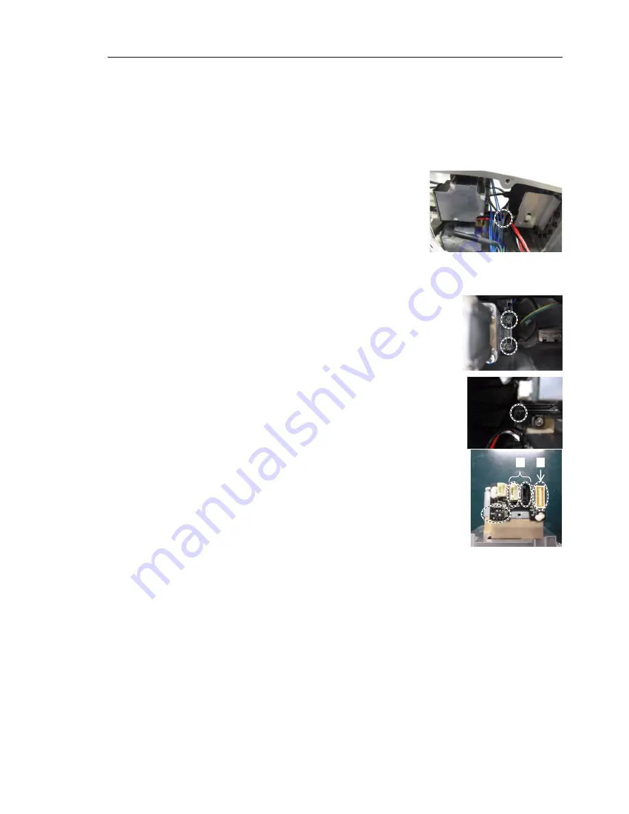
Joint #5 Motor
Removal
(1) Turn OFF the Manipulator.
(2) Remove the following covers.
Arm #4 Cover 1
Arm #4 Cover 2
Reference:
Maintenance 7. Covers
(3) Cut off the wire tie that binds the following cables
and the ground wire.
Wire tie: AB100
Joint #5 motor cable
Signal cable (for motor)
Joint #6 motor cable
Ground wire
Be careful not to cut the harness.
(4) Remove the Joint #5 motor unit.
Hexagon socket head cap bolts: 3-M4×20
(with slotted hole washer)
(5) Disconnect the following connectors of the motor.
A: Signal cable connectors (for motor
×
2)
B: Signal cable connector (for AMP board)
The cables will be necessary again.
Be careful not to lose them.
A
B
NOTE
NOTE
Summary of Contents for VT Series
Page 1: ...6 Axis Robots VT series MANIPULATOR MANUAL Rev 1 EM18YR3817F ...
Page 2: ...MANIPULATOR MANUAL VT series Rev 1 ...
Page 8: ...vi VT Rev 1 ...
Page 16: ...TABLE OF CONTENTS xiv VT Rev 1 ...
Page 18: ......
Page 31: ...Setup Operation 2 Specifications VT Rev 1 15 2 4 Outer Dimensions ...
Page 32: ...Setup Operation 2 Specifications 16 VT Rev 1 Unit mm ...
Page 33: ...Setup Operation 2 Specifications VT Rev 1 17 2 5 Standard Motion Range Unit mm ...
Page 130: ......
Page 138: ...Maintenance 3 Manipulator Structure 122 VT Rev 1 3 Manipulator Structure ...


