background image

Rev. 03072019JA 

www.epvscreens.com


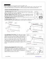
Here’s how to set up your Wireless 5-12 volt trigger | Synchronization Instructions 
Step1

: Connect one end of the 3.5 mm wireless 5-12 volt trigger cable to the RF remote. 

Step 2

: Connect the other 3.5 mm end of the wireless 5-12 volt trigger cable to your projector  

Step 3

: Make sure to unplug your screen from the power outlet 

Step 4

: Hold the 

UP

 button on your RF remote 

Step 5

: While holding the 

UP

 button, plug the screen back to the power outlet 

Step 6

: Wait 5 seconds and then release the 

UP

 button 

Step 7

: Your 5-12V wireless trigger should now be activated with your screen and ready to be used and 

able to control your screen with your projector’s power cycle 

Repeat the steps again if not successful. 

(Please be aware, the projector on/off cycle may take longer to fully activate. It usually takes around 20-

30seconds for full off and on cycle each time) 

 
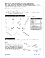
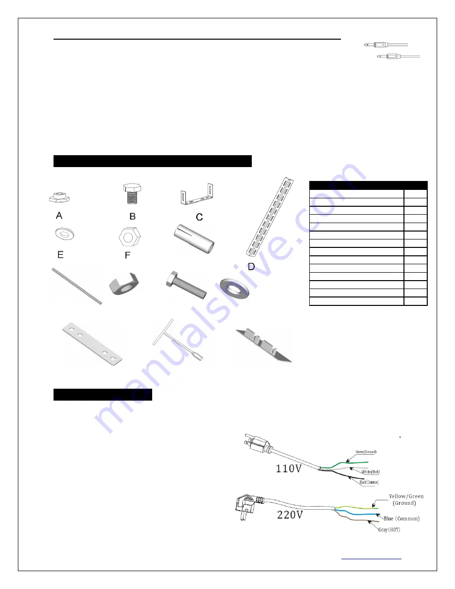
Hardware Parts List for Polar Max Aerie Series 

Please make sure all parts listed below are included before proceeding with the installation. 


Installation Instructions 

The Polar Max Aerie allows access for above or below ceiling installation. Please follow the instructions 
described in the following steps below for your type of installation. 

 
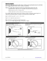
Power 

The Polar Max Aerie Series includes a 3-Prong Power 
Cord  (2-Prong  Power  Cord  for  some  countries)  for 
use  in  a  non-concealed  power  outlet.  If  your 
installation  will  be  entirely  concealed  (including 
power  outlet),  EPV  Screens  strongly  recommends  a 
hardwire connection. Please refer to the image below 
for both 110v & 220v wiring information.


Hardware Parts List


QTY 

A. Case Rail Nut


4-6 

B. Hex Screw


4-6 

C. Hanging Bracket


2-3 

D. Suspension Bar


E.  Washer


8-10 

F.  Hex Nut


4-6 

G.  M8 Top Expanding Bolt


H.  M8 Threaded Rod


I.  M8 Screw Nut


20 

J.  M8 Hexagonal Screw


K.  M8 Screw Washer


28 

L.  Installation Bracket


M.  Socket Wrench


N.  White cover flange panel


Summary of Contents for Polar Max Recessed Series

Page 1: ... short circuit Do not place any heavy objects over the power cord Position the power cord properly to avoid creating a trip obstacle To avoid an electrical shock or fire due to a loose contact or short circuit do not overload the power cord The internal external parts of this unit are not end user serviceable Do not attempt to disassemble this unit by yourself No one except authorized technicians ...

Page 2: ...ment causes harmful interference to radio or television reception which can be determined by turning the equipment off and on the user is encouraged to try to correct the interference by one or more of the following measures Reorient or relocate the receiving antenna of the device which may be casing the interference Increase the separation between the screen and the device s receiver Connect the ...

Page 3: ...ge of 100 feet 4 3 Way Wall Switch Item C Fig 3 The 3 way wall switch is a wall mount switch with an up stop down button and plugs directly into the control box s RJ45 port 5 5 12 volt trigger Item D Fig 4 The built in 5 12V trigger input allows your screen to synchronize its drop rise with the projector s power cycle The screen deploys when the projector powers up and will retract when the projec...

Page 4: ...seconds for full off and on cycle each time Hardware Parts List for Polar Max Aerie Series Please make sure all parts listed below are included before proceeding with the installation Installation Instructions The Polar Max Aerie allows access for above or below ceiling installation Please follow the instructions described in the following steps below for your type of installation Power The Polar ...

Page 5: ... with ultra short throw projectors Minimum lens throw ratio 1 5x image width Ambient light must not come from the same direction as the projector Since angular reflective means that the projected image will reflect at the mirror opposite angle it is important to position the projector so that the viewer will get the best possible image Step 1 Establish the general eye level of the viewers Step 2 S...

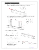
Page 6: ...as shown below Secure the Suspension Bar D with the Hex Screw B Washer E and the Hex Nut F Install the Suspension Bars D to your ceiling according to their distance Optional Installation using parts below 1 Place the Hanging Bracket C in the desired location on the screen s housing and measure the distance as shown below L Distance 2 Mark the location of where the screen will be installed accordin...

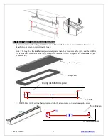
Page 7: ...allation space The width should not exceed 120mm Measure the length of your screen to determine the length Note The length of the installation space is not greater than the screen size table A3 and the width is not less than the screen size table A5 Consult the table below C1 in regards to accommodating the screen casing 2 Drill 4 holes in the ceiling that correspond with the attachments on the va...

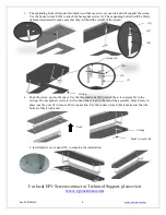
Page 8: ...n 4 Push the screen up into the space Use the threaded rods H to attach the screen assembly to the ceiling The hexagonal screws J will connect the screen to the rest of the assembly Once firmly in place use the nuts I to ensure a firm connection Use the socket wrench M to make sure that the bolts are firmly tightened 5 Install plastic cover panel N to complete the installation For local EPV Screen...

Reviews: