background image

OPERATOR INSTRUCTION MANUAL

IM_NS12_15_20TI_Rev03_A4

NS12TI, NS15TI, NS20TI

INTEGRAL HYDRAULIC NUT SPLITTERS

6

USING THE NS12TI/NS15TI/NS20TI

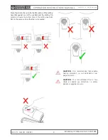
Position the tool as per Section 3.6.

When the pump is operated the piston and the Cutting 

Tip will advance. Ensure the tool is flat against the flange 

and the Cutting Tip perpendicular to the nut throughout 

the operation. Slowly actuate the Nut Splitter to advance 

the Cutting Tip against a flat of the nut and increase the 

pressure until the nut splits.

Releasing the pump will depressurise the cylinder and 

cause it to retract under the force of its internal spring.

It is likely that the nut will require a second split to fully 

remove the nut from the stud. Ideally a second split 

should be carried out at 180° to the first cut, splitting the 

nut in half to enable removal.

After the nut has been split, always check the Cutting Tip 

for damage and replace if required before positioning the 

tool on another nut.

CAUTION: Split nuts often have sharp edges 

and should be handled with great care. 

3.4

HANDLE

The handle can be swivelled around the central axis of the 

tool, to improve access to the nut and allow the tool to be 

easily held in the vertical or horizontal orientation.

3.5

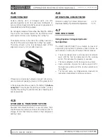
SAFETY LANYARD

The NS tools are supplied with a secure anchor point and 

a safety lanyard. The safety lanyard should be used to 

minimise the risks associated with the tool dropping.

Attach one end of the safety lanyard to the tool using 

the supplied shackle. The other end of the safety lanyard 

should be fixed to a secure point close to the work-site 

using an appropriate shackle.

Avoid using the safety lanyard as a means for picking up 

or carrying the tool. Do not fix the safety lanyard to the 

handle.

3.3

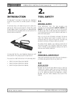
HYDRAULIC TOOL OPERATION

Prior to operation, ensure the air-vent in the integral hand 

pump is not obstructed. Any obstruction in the air-vent 

can cause a vacuum in the system which can limit the 

cylinder’s travel.

The NS12TI, NS15TI and NS20TI Nut Splitter use an 

integral hydraulic pump to drive the cylinder and advance 

the Cutting Tip to split the nut. The hydraulic pressure 

is applied using the integrated hand pump, enabling 

accurate control of the force applied.

The integral hand pump has a control lever which allows 

the user to select advance (+) or retract (-)

ACTUATING THE NS12TI/NS15TI/NS20TI

When advance (+) is selected, pumping the handle will 

advance the piston with the Cutting Tip and split the nut.

RETRACTING THE NS12TI/NS15TI/NS20TI

Selecting Retract (-) will depressurise the cylinder and 

cause it to retract under the force of its internal spring. 

The handle doesn’t need to be pumped to retract the 

cylinder.

Summary of Contents for NS12TI

Page 1: ...ATOR INSTRUCTION M ANUA L NS12TI NS15TI NS20TI E Q U A L I Z E R I N T E R N AT I O N A L LT D w w w e q u a l i z e r i n t e r n a t i o n a l c o m I N T E G R A L H Y D R A U L I C N U T S P L I T...

Page 2: ...LE 3 5 SAFETY LANYARD 3 6 POSITIONING THE TOOL 4 TOOL MAINTENANCE 4 1 INSPECTION 4 2 CLEANING 4 3 CUTTING TIP REPLACEMENT 4 4 MAINTENANCE 4 5 STORAGE TRANSPORTATION 4 6 OPERATING CONDITIONS 4 7 SUB SE...

Page 3: ...personnel deemed competent in the use of mechanical and hydraulic equipment should use these tools 2 3 DISCLAIMER Equalizer cannot be held responsible for injury or damage resulting from unsafe produc...

Page 4: ...ement with body parts The vibration total value to which this tool is subjected does not exceed 2 5 m s2 2 4 DEFINITION OF TERMS A CAUTION is used to indicate correct operating or maintenance procedur...

Page 5: ...ease the splitting operation prolong the life of the Cutting Tip and limit the risk of sparking and debris projectiles 3 2 TOOL SELECTION CAUTION It is important that the correct tool is selected for...

Page 6: ...SAFETY LANYARD The NS tools are supplied with a secure anchor point and a safety lanyard The safety lanyard should be used to minimise the risks associated with the tool dropping Attach one end of th...

Page 7: ...p incident as damage may compromise the safety of the tool CAUTION Only use the designated anchor point for fixing the safety lanyard Do not attach the safety lanyard to the plastic handle DANGER Care...

Page 8: ...ar defenders or ear plugs are worn CAUTION It is recommended that a face shield or suitable eye protection i e safety glasses or goggles are worn Place the tool on the nut with the flat surface of the...

Page 9: ...nserted in the piston before actuating the tool ALIGNMENT SCREW LARGER HEX KEY 4 TOOL MAINTENANCE 4 1 INSPECTION A thorough inspection should be carried out prior to usage storage or transportation to...

Page 10: ...ing worn or damaged parts Use only genuine Equalizer parts from approved distributors or service centres Equalizer parts have been engineered and manufactured to be fit for purpose Do not apply excess...

Page 11: ...truction Manual 1 x Carry Case 580 mm x 350 mm x 180 mm 22 8 x 13 8 x 7 1 Tool only Weight 5 8 kg 12 8 lb Gross Kit Weight 9 0 kg 20 0 lb 5 2 NS12TI TOOL DIMENSIONS 350 mm 13 8 152 mm 6 0 81 mm 3 2 5...

Page 12: ...NS20TISTD 1 x NS20TI Nut Splitter 1 x Spare Cutting Tip 1 x Spare Tip Retention Screw 1 x Spare Alignment Screw 1 x Hex key for Tip Retention Screw 1 x Hex key for Alignment Screw 1 x Safety Lanyard...

Page 13: ...g a hammer and punch Refer to an approved Equalizer distributor for further instruction HYDRAULIC PRESSURE SLOWLY DIMINISHES AND THE PUMP HANDLE DOES NOT RISE P O S S I B L E C A U S E The release val...

Page 14: ...ction THE CUTTING TIP DOES NOT LAST AS WELL AS EXPECTED P O S S I B L E C A U S E Using very hard nuts such as 2H grade will significantly shorten the life of a Cutting Tip R E C O M M E N D E D A C T...

Page 15: ...5_20TI_Rev03_A4 NS12TI NS15TI NS20TI INTEGRAL HYDRAULIC NUT SPLITTER 15 8 PARTS LISTS SERVICE KITS 7 REGULATORY INFORMATION 7 1 REGISTERED HEAD OFFICE EQUALIZER INTERNATIONAL LTD Equalizer House Claym...

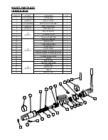
Page 16: ...L PUMP 1 7 KIT 1075100 01 NS12 CUTTING TIP 1 8 ALIGNMENT SCREW 1 9 M4 x 6mm GRUB SCREW 1 10 KIT 1001700 01 M20 FLAT WASHER TO ISO 7089 DIN 125A 1 11 WMU PLAIN BUSHING 1 12 BEARING STRIP 1 13 COMPRESSI...

Page 17: ...0 01 NS15 CUTTING TIP 1 7 ALIGNMENT SCREW 1 8 M4 x 6mm GRUB SCREW 1 9 KIT 1001700 01 WMU PLAIN BUSHING 1 10 BEARING STRIP 1 11 COMPRESSION SPRING 1 12 CYL VENT PLUG 1 13 PISTON LIP SEAL 1 14 M24 FLAT...

Page 18: ...ECAL TI PUMP WRAP 1 7 NOT AVAILABLE NS20TI Body Sticker Wrap 1 8 KIT 1025100 01 NS20 CUTTING TIP 1 9 ALIGNMENT SCREW 1 10 M5 SCKT SET SCREW 1 11 KIT 1021900 01 PLAIN BUSHING 1 12 BEARING STRIP 1 13 CY...

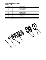
Page 19: ...IN BUSHING 1 2 CYL VENT PLUG 1 3 M20 FLAT WASHER TO ISO 7089 DIN 125A 1 4 M24 FLAT WASHER TO ISO 7089 DIN 125A 1 5 COMPRESSION SPRING 1 6 BEARING STRIP 1 7 PISTON LIP SEAL 1 8 BACK UP RING 1 9 O RING...

Page 20: ...CRIPTION QTY 1 WMU PLAIN BUSHING 1 2 CYL VENT PLUG 1 3 M27 FLAT WASHER TO ISO 7089 DIN 125A 1 4 COMPRESSION SPRING 1 5 BEARING STRIP 1 6 PISTON LIP SEAL 1 7 O RING 1 8 BACK UP RING 1 NS20 CYLINDER SER...

Page 21: ...PISTON ROD 1 39 STEEL BALL 1 ITEM PART NO DESCRIPTION QTY 1 840301 01 PUMP MANIFOLD 1 2 1010101 01 PUMP PISTON HOUSING 1 3 1010102 01 PUMP BLADDER HOUSING 1 4 372401 01 PISTON HOUSING CAP 1 5 372501 0...

Page 22: ...UMP PISTON ROD 1 39 STEEL BALL 1 ITEM PART NO DESCRIPTION QTY 1 840301 01 PUMP MANIFOLD 1 2 376901 01 PUMP PISTON HOUSING 1 3 840302 01 PUMP BLADDER HOUSING 1 4 372401 01 PISTON HOUSING CAP 1 5 372501...

Page 23: ...3 2 1 3 ITEM NO DESCRIPTION QTY 1 HANDLE CLEVIS 1 2 CLEVIS PIN 2 3 RETAINING RING 4 CLEVIS SERVICE KIT 840160 01 REV 01 Page 23...

Page 24: ...4 3 2 7 5 1 1 6 5 ITEM NO DESCRIPTION QTY 1 STEEL BALL 2 2 CONE SEAT 1 3 CONE 1 4 LONG SEPARATOR SPRING 1 5 SPRING 2 6 SCREW 1 7 SPRING LOCK 1 INTEGRAL MANIFOLD SERVICE KIT 840130 01 REV 03 Page 24...

Page 25: ...1 3 2 1 4 ITEM NO DESCRIPTION QTY 1 SPIRAL RETAINING RING 2 2 ANCHOR POINT 1 3 HANDLE 1 4 HANDLE STICKER 1 NS12 NS15 HANDLE SERVICE KIT 1001800 01 REV 02 Page 25...

Page 26: ...3 2 1 3 ITEM NO DESCRIPTION QTY 1 ANCHOR POINT 1 2 Modular Handle Assembly 1 3 Spiral Ring 2 NS20 HANDLE SERVICE KIT 1023000 01 REV 03 Page 26...

Page 27: ...2 3 1 ITEM NO DESCRIPTION QTY 1 NS12 CUTTING TIP 1 2 M4 x 6mm Grub Screw 1 3 ALIGNMENT SCREW 1 NS12 CUTTING TIP SERVICE KIT 1x 1075100 01 01 REV 02 Page 27...

Page 28: ...2 3 1 ITEM NO DESCRIPTION QTY 1 NS12 CUTTING TIP 3 2 M4 x 6mm Grub Screw 3 3 ALIGNMENT SCREW 3 NS12 CUTTING TIP SERVICE KIT 3x 1075300 01 01 REV 02 Page 28...

Page 29: ...2 3 1 ITEM NO DESCRIPTION QTY 1 CUTTING TIP 1 2 M4 x 6mm Grub Screw 1 3 ALIGNMENT SCREW 1 NS15 CUTTING TIP SERVICE KIT 1x 1005100 01 01 REV 02 Page 29...

Page 30: ...2 3 1 ITEM NO DESCRIPTION QTY 1 CUTTING TIP 3 2 M4 x 6mm Grub Screw 3 3 ALIGNMENT SCREW 3 NS15 CUTTING TIP SERVICE KIT 3x 1005300 01 01 REV 02 Page 30...

Page 31: ...2 3 1 ITEM NO DESCRIPTION QTY 1 CUTTING TIP COATING 1 2 M5 SCKT SET SCREW 1 3 ALIGNMENT SCREW 1 NS20 CUTTING TIP SERVICE KIT 1x 1025100 01 01 REV 02 Page 31...

Page 32: ...2 3 1 ITEM NO DESCRIPTION QTY 1 CUTTING TIP COATING 3 2 M5 SCKT SET SCREW 3 3 ALIGNMENT SCREW 3 NS20 CUTTING TIP SERVICE KIT 3x 1025300 01 01 REV 02 Page 32...

Page 33: ...SAFETY BOND 830080 01 REV 01 Page 33...

Page 34: ...l a y m o r e D r i v e A b e r d e e n S c o t l a n d U K A B 2 3 8 G D t 4 4 0 1 2 2 4 7 0 1 9 7 0 f 4 4 0 1 2 2 4 8 2 3 7 9 1 H o u s t o n O f f i c e 1 3 3 0 Ya l e S t r e e t H o u s t o n T...

Reviews: