ISPJUNO - Portable ISP Programmer - User Guide V0.84 – 17/04/20
20
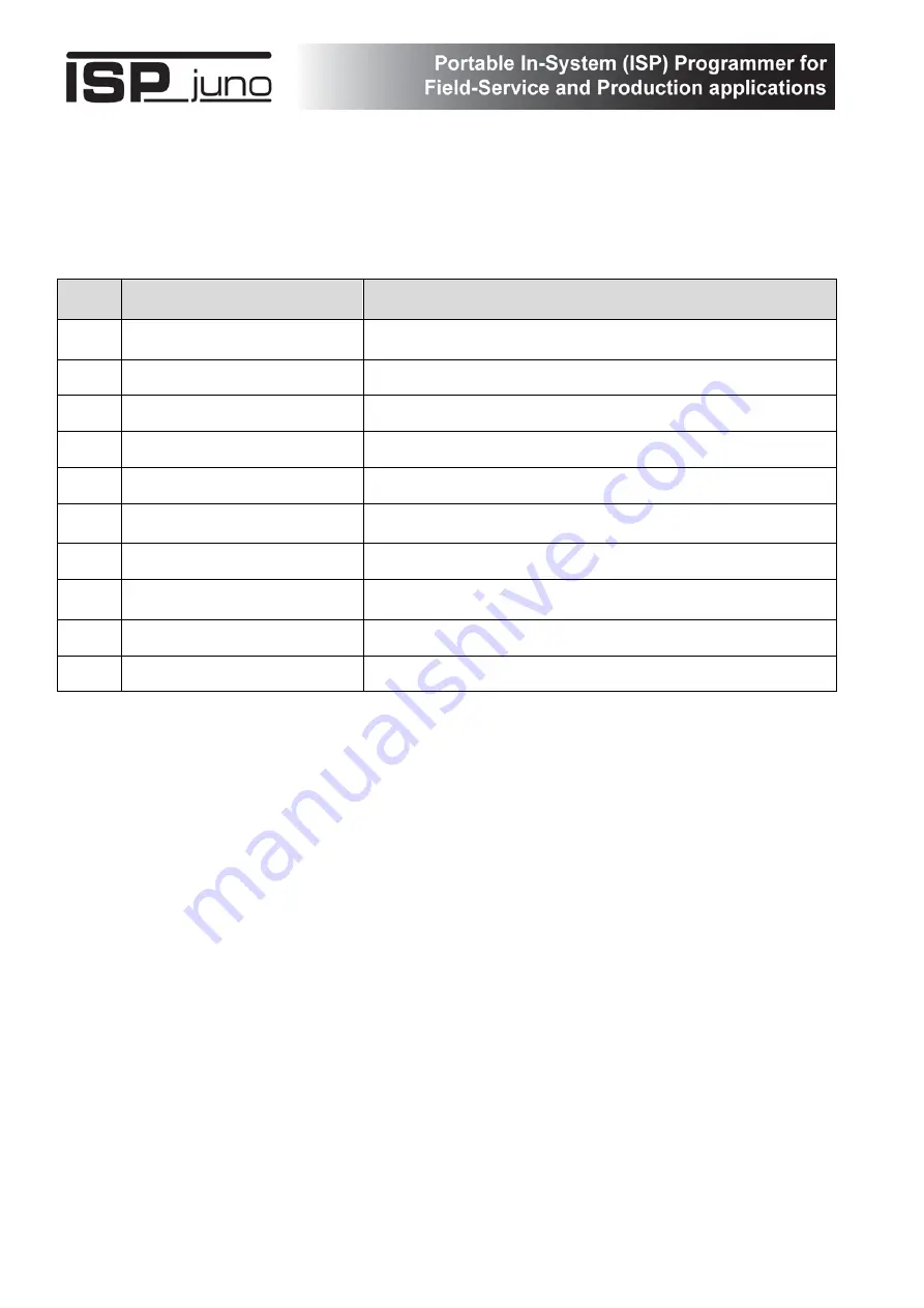
3.3 ISPjuno - Power Supply overview
The ISPjuno programmer internal power supply configuration is shown in the overview diagram on the
next page.
The table below refers to the diagram on the next page…
Key
#
Description
Comments
1
DC Power Jack Socket
2.1mm centre positive jack socket
Input 9.0 - 24.0V DC
2
USB +5V Port
Connect to PC USB Port
3
DC / DC Converter
Converts 9.0 – 24.0V input voltage to 5.2V
4
DC / DC Boost Circuit
Boosts the input voltage to ensure it is 5.2V
5
LDO
Low drop-out regulated power supply block
6
LDO Power Supply
Low drop-out regulated power supply with pre-set voltage
steps
7
Target Vcc Switch
Switch controlling the output of the LDO power supply.
8
Target Discharge Circuit
When enabled, this circuit provides a discharge path for any
energy contained in the target system power supply.
9
Measure V_Target
Analogue measurement of Target TVCC voltage
10
Customer Target PCBA
PCBA / DUT under test / being programmed


