background image


ISPJUNO - Portable ISP Programmer - User Guide V0.84 – 17/04/20 

27 

4.0 Powering the Target System 

4.1 Overview 

This section explains the different options available for powering the 

‘Target System’


It is possible to power the 

‘Target System’

. either from an 

‘external power supply’

 or by utilising the 

‘Programmer Controlled Target Power Supply’


Target System 
powering method 

Voltage range 
(V) 

Power supply used to power the Target 
System 

Independently powered  3.0 – 5.0 

External Power Supply 
e.g. bench supply 

Powered from the 
programmer 

Pre-set 
voltages: 
3.0V, 3.3V, 
4.7V or 5.0V 

Programmer Controlled Target Power Supply 

 
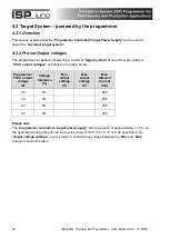
The programmer is only capable of generating 4 different pre-set target voltages: 3.0V, 3.3V, 4.7V or 
5.0V. 


Summary of Contents for ISP juno

Page 1: ...User Guide...

Page 2: ...overview 20 3 4 External mains power adaptor via DC jack socket 22 3 5 External DC supply via DC jack socket 23 3 6 PC USB port power via programmer USB port 24 3 7 Customer Target System Target Suppl...

Page 3: ...de sequence 45 6 8 Project PASS 46 6 9 Project FAIL error messages 46 6 10 Repeatedly executing the same project 47 6 11 Programmer power up auto selection of project 48 Appendix 1 10 way ISP Header S...

Page 4: ...purpose other than for the purchaser s personal use without written permission 2000 2018 Copyright Equinox Technologies UK Limited All rights reserved MicrochipTM and AVRTM are trademarks of the Micro...

Page 5: ...mage to the programmer due to voltages beyond the specified voltage limits being applied to the DC Power Input CON1 or any of the ISP Headers The user must ensure that sufficient care is taken to avoi...

Page 6: ...It is recommended that high volume users always validate that a sample of a devices has been programmed correctly before programming a large batch Equinox Technologies UK Ltd can not be held responsi...

Page 7: ...that you are not yourself carrying a static charge before handling the product Wearing an earthed anti static wrist strap is recommended Equinox have taken great care in designing this product to be...

Page 8: ...tails for information on keeping up to date with software revisions iii Internet Web Site The support page for all Equinox ISP Programmers can be found at http www equinox tech com products downloadse...

Page 9: ...his software is used to create and upload Standalone Programming Projects to the programmer The following sources of documentation are available for this software Installation and Getting Started Guid...

Page 10: ...on Notes available for helping to create Programming Projects for different device families Application Note Device Family Programming Interface AN100 Atmel AT89Sxxxx FLASH microcontrollers SPI AN101...

Page 11: ...dure and Oscillator Calibration procedure Application Note Description AN112 Firmware Update instructions for Equinox ISP Programmers AN114 Accurate on chip Oscillator Calibration for Atmel AVR microc...

Page 12: ...f storing up to 64 completely independent Standalone Programming Projects Supports In system Programming ISP of many different programmable microcontrollers serial EEPROM FLASH memory devices and othe...

Page 13: ...ISPJUNO Portable ISP Programmer User Guide V0 84 17 04 20 12...

Page 14: ...le ISP Programmer User Guide V0 84 17 04 20 13 2 0 Programmer Overview Specifications 2 1 Programmers covered in this manual This manual describes the configuration and use of the Equinox ISPjuno devi...

Page 15: ...om 10 Hz up to 4 MHz Fully ESD and Over voltage protected I O All Target I O pins feature both ESD and over voltage protection Supports programming at Target Voltages down to 3 0V An optimised driver...

Page 16: ...adaptors UK USA European Asia Cables USB connection cable mini USB to USB A 16 way IDC ISP cable 10 way IDC ISP cable DC Power Cable 2 1mm jack plug to bare wire ends Miscellaneous 2 x Jumper Links 4...

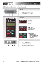
Page 17: ...l 1 Target ISP Connector 16 Way 2 Target ISP Connector 10 Way Front Panel Status LEDs PASS BUSY FAIL Other LEDs Comms status Target Vcc 4 button keypad RED Tick OK Green cross Cancel Up Down for proje...

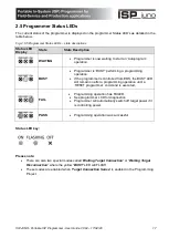
Page 18: ...ming operation If the programmer is controlled from EDS the BUSY LED will remain on after a programming operation until a RESET programmer command is executed FAIL Programming operation has FAILED See...

Page 19: ...Switched Vcc supply Not supported Analogue voltage measurement Yes Target TVCC Target current measurement Not supported Target over current detection Not supported Target controlled discharge circuit...

Page 20: ...mer DC jack socket 3 6 5 Customer Target System Target Supply 3 7 3 2 Programmer power connectors The programmer can be powered from either the DC jack power connector or the mini USB port connector w...

Page 21: ...t 3 DC DC Converter Converts 9 0 24 0V input voltage to 5 2V 4 DC DC Boost Circuit Boosts the input voltage to ensure it is 5 2V 5 LDO Low drop out regulated power supply block 6 LDO Power Supply Low...

Page 22: ...ISPJUNO Portable ISP Programmer User Guide V0 84 17 04 20 21...

Page 23: ...ant note The jack socket on the programmer is a 2 1mm centre positive socket Instructions Ensure the the ISP cable from the programmer is disconnected from any target system Plug the 2 1mm jack plug e...

Page 24: ...f the cable is supplied with bare wire ends for connecting to an external power supply e g bench PSU The black lead with the white stripe is the VE cable The all black lead is the GROUND cable The ext...

Page 25: ...into a spare USB port on the host PC or powered USB hub Plug the mini USB connector end of the USB cable into programmer The programmer should power up and show text on the display The USB cable spec...

Page 26: ...d of powering the programmer is not recommended due to the high current required by the programmer during the programming process The target supply must have enough headroom to supply at least 200mA t...

Page 27: ...h is suitable for powering the ISPjuno programmer Instructions follow the order below 1 Ensure the the ISP cable from the programmer is disconnected from any target system 2 Plug the USB Type A connec...

Page 28: ...l power supply or by utilising the Programmer Controlled Target Power Supply Target System powering method Voltage range V Power supply used to power the Target System 1 Independently powered 3 0 5 0...

Page 29: ...onfigure the programmer so the Target System is independently powered This means that the Target System is powered by an external power supply and NOT by the programmer Important note In this scenario...

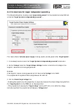
Page 30: ...tton 2 Set the Voltage under the Target Voltage Settings section to match the I O voltage of the target IC device which is being programmed Example If the target IC device is being powered at 3 3V the...

Page 31: ...one of four pre defined TVCC output voltages as defined in the table below Programmer TVCC output voltage V Voltage tolerance Min output voltage V Max output voltage V Max Allowed Current mA 3 0 5 250...

Page 32: ...selected Target Voltage as shown in the table below Programmer TVCC output voltage V Logic 0 voltage V Logic 1 voltage V 3 0 0 3 0 3 3 0 3 3 4 7 0 4 7 5 0 0 5 0 Warning It is possible to damage the T...

Page 33: ...e Voltage field Now select the required voltage from the list displayed 3 0V 3 3V 4 7V or 5 0V The Voltage field will default to the lowest voltage allowed for the selected Target device IC When the p...

Page 34: ...of the programmer as shown in the illustration below The pin out of these IDC connectors are shown below 1 2 A full explanation of each pin out is available in the relevant chapters referred to in th...

Page 35: ...e the programmer and the Target IC s to be programmed on the Target System 5 x Programmable Input Output lines 1 x Programmable Output only line 1 x Dedicated RESET pin The diagram below shows the ava...

Page 36: ...es 32 kHz Please note The SPI interface JTAG interface and UART interface signals all share the same physical programmer I O lines This means that the programmer can only be connected to a target devi...

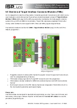
Page 37: ...ces The illustration below shows how the ARM Target Interface Module plugs into the end of the ISPjuno programmer Pluggable connector modules which feature the popular connector types and connector pi...

Page 38: ...teeing good signal integrity See Appendix 2 for further information AVR TIM Module AVR TIM 01 V1 0 Connects to ISPjuno programmer Features most of the popular connector types pin out s used for progra...

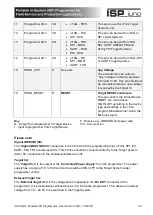
Page 39: ...t of this connector is detailed in the table below Pin No Programmer Pin name I O Connect to pin on Target System Notes 1 2 TARGET_VCC P TARGET_VCC Target VCC This pin should be connected to the Targe...

Page 40: ...OW according to the device type and settings in the Pre program State Machine tab in the EQtools project Key O Output from programmer to Target Device I Input to programmer from Target Device P Passiv...

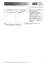
Page 41: ...is possible for 12V to be output on pin 10 of this connector when programming ATtiny11 12 15 devices 2 Connecting to the wrong ISP Header may cause catastrophic damage to the Programmer Target System...

Page 42: ...O RESET Target RESET control pin This pin controls the Target Device RESET pin It will driven HIGH LOW according to the device type and settings in the Pre program State Machine tab in the EQtools pro...

Page 43: ...being connected to a PC When the programmer is being operated in Standalone mode the user simply selects the required Standalone programming project from the list of projects which have been pre store...

Page 44: ...s key is used to scroll Up the project list if there is more than one project stored in the programmer DOWN This key is used to scroll Down the project list if there is more than one project stored in...

Page 45: ...ne 4 Project name Project ID 6 5 Selecting a project from the Project List If there are multiple projects in the uploaded Project Collection then it is possible to scroll through the list of all proje...

Page 46: ...ect e g PROJECTNAME1 The programmer will then perform a Project Image check This checks that the project data is valid not corrupt Press the key to execute the selected Standalone programming project...

Page 47: ...message is Cannot enter initial device communication Target Connection or Clock Speed Problem Error 40 Cannot enter programming mode LCD Display message This error corresponds to programmer error Err...

Page 48: ...programming project 6 10 Repeatedly executing the same project If you are batch programming and simply want to execute the same standalone programming project over and over again then you need to per...

Page 49: ...6 11 Programmer power up auto selection of project When the programmer if first powered up it checks to see what the last project executed was before power was removed This last project is then autom...

Page 50: ...IDC connector shown as 2 in the diagram below on the ISPjuno programmer to connect to many different target device types The same pins on this connector are re used for different functions depending o...

Page 51: ...DC connector depending on the target device algorithm ISP Header Description Function Refer to section ISP Header Pin out 1 Equinox 10 way IDC AVR SPI 3 1 2 10 way JTAG IDC non standard pin out 3 2 2...

Page 52: ...nnect to Clock Buffer circuit Buffer Enable pin This pin is used to enable the output of a remote Clock Buffer 3 Programmer I O4 IO4 No connect N C No connection for SPI 4 Programmer I O1 IO1 SPI MOSI...

Page 53: ...nnected to the Target System Vcc 2 BUFFER_ENABLE IO5 Connect to Clock Buffer circuit Buffer Enable pin This pin is used to enable the output of a remote Clock Buffer 3 Programmer I O4 IO4 O JTAG TMS J...

Page 54: ...at you have made the correct connections from the ISP Header to your Target Device Figure 3 3 Equinox 10 way IDC Header J8 viewed from above Warning It is possible for 12V to be output on pin 10 of th...

Page 55: ...RAMMER and Target System 8 PROG_SDO I SDO SDO Serial Data Output This is the serial data output signal from the Target Device to the programmer It is an INPUT pin to the programmer 9 PROG_GND P GROUND...

Page 56: ...s from the programmer to RS 232 using an external convertor Figure 3 4 Equinox 10 way IDC Header J8 viewed from above Warning 1 It is possible for 12V to be output on pin 10 of this connector when pro...

Page 57: ...on the Target Microcontroller 9 PROG_GND P Ground Connection Target Programmer GROUND connection Common ground connection between PROGRAMMER and Target System 10 PROG_RESET O RESET Target RESET contr...

Page 58: ...0 3 J9 Tag Connect TC2030 IDC PLUG OF NAILS TM CABLE 6 way IDC header Custom IDC 0 1 6 4 J5 10 way 0 05 Samtec connector standard ARM pin out 10 way ARM Cortex Samtec 0 05 10 5 J6 20 way 0 1 IDC conne...

Page 59: ...Portable ISP Programmer User Guide V0 84 17 04 20 58 Appendix 3 AVR Target Interface Module TIM The diagram below shows the various ISP connectors which are available on the AVR Target Interface Modu...

Page 60: ...VR SPI 10 way IDC 0 1 10 5 J6 Atmel AVR 6 way IDC SPI pin out AVR SPI 6 way IDC 0 1 6 6 J8 Configuration Jumper link 7 J9 Configuration Jumper link 8 J13 Atmel AVR ATtiny UPDI 6 way IDC AVR UPDI IDC 0...

Reviews: