14
MULTICHANNEL OPERATION. AUDIO LINKS
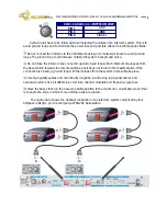
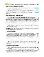
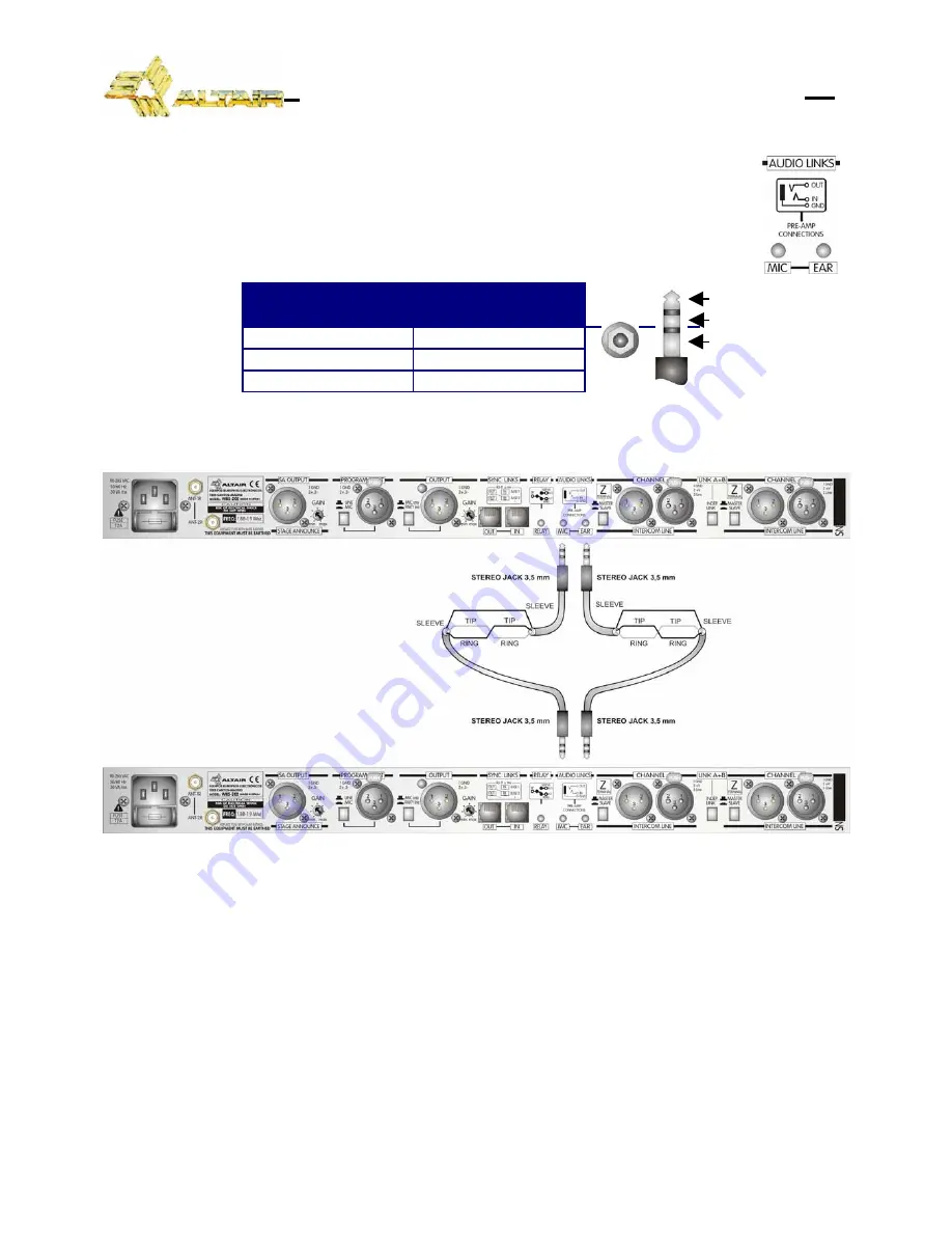
Rear panel audio links allows multichannel operation sharing the headset
between bases, so accessing all the channels.
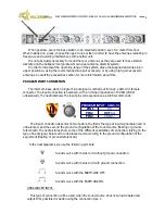
Connection is made by using two leads composed of 2 stereo 3,5 mm jacks at
each end wired in inverted mode and by using miniature 2 conductors plus shield
microphone cable. See the diagram bellow for reference.
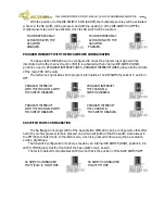
JACK 3,5 mm — MULTICHANNEL
UNIT A
UNIT B
TIP
RING
RING
TIP
SHIELD
SHIELD
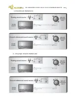
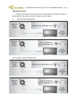
Schematic diagram:
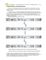
System operation is strait forward. You can connect your headset to any of the bases.
Microphone signal from the preamp out of the base #2 is directed to the preamp input in base#1.
Channel Mic A and B on/off switches from base#2 corresponds now to channels C and D
respectively. Listening from the four channels are controlled by local volume and balance controls
as depicted in this manual, A and B on base#1 and C and D on base#2.
Call signaling, remote mic kill and buzzer kill are to be controlled on each base
independently.
Program input signal must be splitted to each base if needed.
SA (Stage announce) outputs from the two bases must be combined externally by using an
audio mixer and then connected to the PA system.
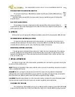
This audio links allows advanced functionalities:
Mic link-Direct microphone out, Mic input from external equipment, etc
EAR link-Listen connection to external powered speakers, cue input to the operator, etc
TIP (in)
RING (out)
SHIELD (common)
WB-200 SERIES INTERCOM SYSTEM — WBS-202 DUAL CHANNEL WIRELESS BASE STATION


