background image

18 

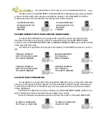
In fact, we have explained the factory set-up in the previous paragraph. The PA OUTPUT can

be configured to always be enable, one can enable the PA OUTPUT and the multipurpose relay
activating the channel A and/or B microphone independently or activating the buzzer mute signal
(BUZZER REMOTE MUTES). Whenever the PA OUTPUT and the multipurpose relay are activated, the
PA-MIC switch associated LED will turn on (in the case of activating the PA OUTPUT permanently,
the multipurpose relay won't be always activated, and the PA-MIC associated LED will turn off). In
order to obtain more information, consult the special operations section.

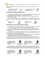
The microphones of the manager beltpacks WBP-202 can also be directed to the PA output

(in the WBS-202 base station can be registered one manager beltpack per  wireless channel).
When this happens, from any of the 2 wireless beltpacks WBP-202, also turns on the LED and
active the multipurpose relay associated (RELAY). For more information, see the the wireless
beltpack WBP-202 owner manual.

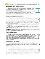
In it default configuration, this switch operates as Push to Talk however, can be configured so

that if hold this switch for four seconds, it turned out indefinitely (after this four seconds, the unit
emits a short beep, indicating that the system have entered into this function). For more information
see special operations.

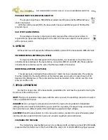
The multipurpose relay, can be also be activated with the MIC TALK switches of lines A and /

or B, or independently of the stage announce switch state.

CALL SWITCH 

The WBS-200 base station is provided with two call switches, one per intercom

channel. When one of these switches is pressed a call signal is sent to the
corresponding intercom channel (A or B). The call signal makes the LED associated with
the switch start blinking; if the buzzer its not remote muted (consult remote mute all mics
and buzzer switches for more information) an intermittent sound takes place during three seconds,
the same as in all the units (wired and wireless beltpacks, desk stations, master stations, etc.),
connected to the intercom channel selected.

If the CALL switch is pressed continuously, the duration of the call signal will be higher (the

time that the switch is pressed, and approximately 3 seconds more).

If a call signal is generated in an external unit (wired and wireless beltpacks, desk stations,

master stations, etc.), the LED associated to the CALL switch, will start blinking and if the buzzer is
not remote muted (consult remote mute all mics and buzzer switches for more information) an
intermittent sound will take place during about three seconds. 

If a call signal is generated in a wireless beltpack of the intercom system, the

corresponding IN RANGE led to the beltpack number start blink. If this call is generated by
a single wireless beltpack WBP-200 registered in the R1 radio group, the call will be sent
to the intercom line channel A, however, if it is generated by a single wireless beltpack
WBP-200 registered in the R2 radio group, the call will be sent to the intercom line channel A , if
the mode selector switch radio R2 is set to CH1 (join the R1 and R2 radio groups), if
this mode selector switch radio R2 is set to CH2, the call of the wireless beltpack
will be transmitted to the intercom line channel B.

If the wireless beltpack is a dual channel WBP-202 wireless beltpack, the call

is independent of the registered group (R1 or R2) as well as the mode selector
switch radio R2 and the beltpack send the call signal to the channel selected in its
channel selection LEDs (A, B or A + B).

MIC ON/OFF/PUSH TO TALK SWITCH

The WBS-202 base station is provided with two talk switches, one per intercom channel.
The TALK switch allows to enable/disable the microphone, so that we are able to speak

WB-200 SERIES INTERCOM SYSTEM — WBS-202 DUAL CHANNEL WIRELESS BASE STATION

Summary of Contents for WBS-202

Page 1: ...INTERCOM HF DIGITAL FUNKINTERCOM BASISSTATION AUDIO ELECTRONICS DESIGN AUDIO ELECTRONICS DESIGN AUDIO ELECTRONICS DESIGN AUDIO ELECTRONICS DESIGN EQUIPOS EUROPEOS ELECTRÓNICOS S A L Avda de la Industria 50 28760 TRES CANTOS MADRID SPAIN 34 91 761 65 80 34 91 804 43 58 altair altairaudio com www altairaudio com ...

Page 2: ... SWITCH 18 SIDETONE CONTROL 19 LINE A AND B LISTEN BALANCE CONTROL 19 PROGRAM INPUT TO LINES A B SWITCHES 19 PROGRAM INPUT LEVEL CONTROL 19 PROGRAM TO HEADPHONES CONTROL 20 RADIO REGISTER SWITCHES 20 IN RANGE LEDS 20 MODE SELECTOR SWITCH RADIO 2 to CH 1 CH 2 21 INTERCOM LINE TERMINAL IMPEDANCE SWITCH 21 LINES A AND B LINK SWITCH 21 PROGRAM OUTPUT GAIN CONTROL 21 PROGRAM OUTPUT SIGNAL SELECT 21 PRO...

Page 3: ...iguration The new system includes a new double channel Manager beltpack WBP 202 with channel selection listen balance adjustment of each channel and SA stage announce function All this features allows great versatility to the production Manager allowing full communications capability into two separate crews The system comprises a powered base station WBS 202 and battery powered beltpacks WBP 200 s...

Page 4: ...A 2 MIC ON OFF PUSH HEADSET CONNECTORS TO TALK SWITCH AND LINE A AND B LISTEN SIDETONE CONTROL BALANCE CONTROL PROGRAM INPUT TO LINES A B SWITCHES PROGRAM INPUT LEVEL CONTROL HEADSET VOLUME CONTROL PROGRAM INPUT TO GLOBAL REMOTE BUZZERS and HEADPHONES CONTROL MODE SELECTOR SWITCH ALL MICS SWITCHES RADIO 2 to CH 1 CH 2 STAGE ANNOUNCE SA RADIO REGISTER SWITCH ENABLE SWITCH AND IN RANGE LEDS POWER SW...

Page 5: ...INAL IMPEDANCE MODE SELECTOR SELECT SLAVE STAGE ANNOUNCE OUTPUT AND GAIND ADJ WHEN UNIT IS LINKED TO ANOTHER TERMINATED INTERCOM LINE PROGRAM INPUT AND MIC LINE INTERCOM LINES CONNECTIONS A B LEVEL SELECTOR PARTY LINE OR MIC ONLY SELECTOR GAIN ADJ LINES A B LINK SMA SECONDARY AND OUTPUT CONNECTOR ANTENNA CONNECTORS WB 200 SERIES INTERCOM SYSTEM WBS 202 DUAL CHANNEL WIRELESS BASE STATION ...
Page 6: ... close to heat sources 4 INSTALLATION UNPACKING Before leaving the factory each intercom base station has been carefully inspected and tested Unpack and inspect the unit for any damage that may have occurred during shipment If any damage is found does not connect the unit to the mains notify the sales person immediately a qualified service technician should inspect the unit Save the original packi...

Page 7: ... supply male connector placed at the rear panel Insert the male connector of the tripolar cable into the mains plug Turn on the unit power switch In that moment all the LED indicators will light for a while indicating that the unit is turned on CAUTION Make sure that the mains voltage is the correct as well as their fuse is the right one ANTENNA MOUNTING The base station incorporates four antenna ...

Page 8: ...edance of 40 KΩ 20 KΩ unbalanced The next list shows the input pins correspondence as A E S recommends PROGRAM INPUT XLR 3 31 PIN 1 0 V PIN 2 HOT PIN 3 COLD The input connection depends on two factors the first is the type of input signal balanced or unbalanced and the second the ground configuration of the sound source floating or ground referenced The next pictures show some of the different pos...

Page 9: ...9 1 Using twin lead shielded cable 2 Using single conductor shielded cable WB 200 SERIES INTERCOM SYSTEM WBS 202 DUAL CHANNEL WIRELESS BASE STATION ...

Page 10: ... ground configuration of the sound destination unit floating or ground referenced The next pictures show some of the different possibilities of connection relying on the type of output signal balanced or unbalanced and according to the equipment s ground configuration floating or ground referenced In the next diagrams we use the following symbols Sound destination unit with mains cord without grou...

Page 11: ...the sound destination unit does not provide a balanced input If it s possible it is better using the connection type 1 1 Using twin lead shielded cable 2 Using single conductor shielded cable WB 200 SERIES INTERCOM SYSTEM WBS 202 DUAL CHANNEL WIRELESS BASE STATION ...
Page 12: ...N SLEEVE The relay operation mode is configured by an internal micro switch Factory set to SA See the other possible configurations bellow in SPECIAL OPERATION paragraphs NOTE Relay operation is changeover type When the function is not active the Ring pole is connected to the Tip ant the Sleeve is opened When active Ring connects to the Sleeve and Tip becomes opened CONNECTION TO EXTERNAL WIRED IN...

Page 13: ...station towards the remote stations but it does not return to the master station If the connection is closed a ground loop with the increase from the system noise will take place Use high quality cables and minimize its longitude Avoid using low quality cables and excessive cable runs as it affects in power loss channel crosstalk and frequency response Place the base station in the closest possibl...

Page 14: ...l Mic A and B on off switches from base 2 corresponds now to channels C and D respectively Listening from the four channels are controlled by local volume and balance controls as depicted in this manual A and B on base 1 and C and D on base 2 Call signaling remote mic kill and buzzer kill are to be controlled on each base independently Program input signal must be splitted to each base if needed S...

Page 15: ...e units by a double glitch on each of the register switches That helps on cable verification and maintenance Next diagram shows the connection example Maximum allowed lead length is about 50 meter Consult us for extended length System operation is the same as depicted in the manual with the following considerations Start up time is not immediate Allow up to 5 minutes to consider that all the syste...

Page 16: ...m comprises a powered base station WBS 202 and battery powered single channel WBP 200 beltpacks and dual channel WBP 202 Manager beltpacks Base station is designed to operate in stand alone or Master mode enabling full duplex clear and secure communication with up to 8 beltpacks and the base operator in simultaneous party line mode For large system operation the unit can be used in Slave mode by w...

Page 17: ...ing it This means that the units wired and wireless beltpacks desk stations units etc connected to the system can turn on the microphones again when it s required When this switch is pressed its associated LED turns on during a moment The BUZZERS switch on the other hand carries out an on off function If the remote mute buzzers function was enabled when the remote mute buzzers switch is pressed th...

Page 18: ... muted consult remote mute all mics and buzzer switches for more information an intermittent sound takes place during three seconds the same as in all the units wired and wireless beltpacks desk stations master stations etc connected to the intercom channel selected If the CALL switch is pressed continuously the duration of the call signal will be higher the time that the switch is pressed and app...

Page 19: ...ne for each channel It is necessary to adjust each sidetone control independently disabling a channel and adjusting the other and vice versa LINE A AND B LISTEN BALANCE CONTROL The listen balance control between lines A and B allows to adjust the signal mix of both channels that appears in the headset of the main station Totally to the left the signal that appears in the headset is only the channe...

Page 20: ...ion group If we do not do anything during 60 seconds the function will be reset If we pressed key REGISTER again the function will be reset With the beltpack that we want to register turned off turn on pressing the ON OFF switch maintaining pressed the VOLUME UP DOWN switches If everything goes well the base station base will sound if the buzzer it is turned on and the beltpack also if the buzzer ...

Page 21: ...edance is in off mode and with the switch depressed it is in on mode CAUTION Never leave the intercom line without terminal impedance because a bad operation of the units connected to the line would take place LINES A AND B LINK SWITCH The lines A and B link switch allows to join the two channels so that the same signal appears in both channels If the channels A and B are linked the units connecte...

Page 22: ...inting out the desired area and covers a focused beam of 60 degrees H by 60 degrees V The panel antenna must be installed on the unit to cover the local area around the unit 7 SPECIAL OPERATIONS In order to set up some of the base station possibilities the unit must be opened removing the six screws of the unit top cover NOTE This type of operations takes place with the unit is opened the best thi...

Page 23: ...in PCB of the unit The configurations are additive this means that if we have configured the positions 1 2 and 3 the multipurpose relay will be activated whenever the channel A or channel B microphone are activated as well as when the key of SA is pressed The factory set up is with the DSW2 position 3 SA_KEY in ON and the other positions in OFF so that the multipurpose relay is active only with th...

Page 24: ...IP SWITCH positions 5 and 6 in OFF PROGRAM INTERRUPT PROGRAM INTERRUPT WITH THE CHANNEL A WITH THE CHANNEL A MIC SWITCH DISABLED SWITCH DISABLED PROGRAM INTERRUPT PROGRAM INTERRUPT WITH THE CHANNEL B WITH THE CHANNEL B MIC SWITCH DISABLED MIC SWITCH DISABLED SA SWITCH MODE CONFIGURATION The SA Stage Announce switch of the base station WBS 202 can be configured so that after hold it 5 seconds press...

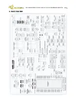
Page 25: ...25 8 BLOCK DIAGRAM WB 200 SERIES INTERCOM SYSTEM WBS 202 DUAL CHANNEL WIRELESS BASE STATION ...
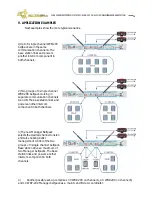
Page 26: ...wers another intercom component in both channels 3 The new Manager Beltpack selects the desired channel to listen and talk enabling better management control of the two groups of 3 single channel beltpack Base station drives a maximum of two Manager beltpacks The base station links and powers another intercom component in both channels 4 Another possible set up comprises 3 X WBP 200 on channel A 4...

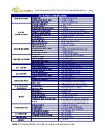
Page 27: ...ADJUSTMENT Rear panel Range 0 to 100 NOMINAL MAXIMUM LEVEL 4 dBu 8 dBu S A OUTPUT TYPE IMPEDANCE Balanced XLR 3 32 100 Ω OUTPUT ADJUSTMENT Rear panel Range 0 to 100 NOMINAL MAXIMUM LEVEL 4 dBu 8 dBu PROGRAM INPUT TYPE Balanced XLR 3 31 IMPEDANCE LINE MIC 40 KΩ 2 KΩ INPUT LEVEL MIC adjustable 15 dBu to 45 dBu LINE adjustable 10 dBu to 20 dBu MULTICHANNEL OPERATION AUDIO LINKS MIC EAR PreAmps 2x min...

Page 28: ...must be sent to the dealer or the manufacturer The serial number of the unit must be included for any request to the technical service Equipos Europeos Electrónicos reserves the right to modify the prices or the technical specifications without further notice SERIAL NUMBER AUDIO ELECTRONICS DESIGN AUDIO ELECTRONICS DESIGN AUDIO ELECTRONICS DESIGN AUDIO ELECTRONICS DESIGN EQUIPOS EUROPEOS ELECTRÓNI...

Page 29: ...ntries of the European Union We encourage the recycling of our products If you have further questions about recycling contact your local sales office Directiva sobre Residuos de Aparatos Eléctricos y Electrónicos RAEE El logotipo de la Directiva RAEE se refiere a los programas y procedimientos específicos de reciclaje para aparatos electrónicos de países de la Unión Europea Recomendamos el recicla...

Reviews: