21
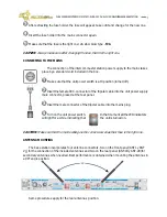
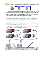
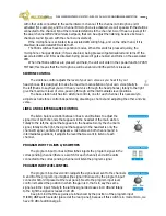
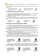
MODE SELECTOR SWITCH RADIO 2 to CH-1/CH-2.
Radio group 2 can work independently, without pressing this switch, so that
the signal from the wireless beltpacks belongs to radio 2 is sent to the intercom
channel B. In this mode, CH B LED remain on.
With this switch pressed, the radio 2 signals are sent to the intercom channel
A, so the system will operate as a single radio system with eight wireless
beltpacks, all connected to the intercom channel A. In this mode the CH A LED
remain on.
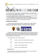
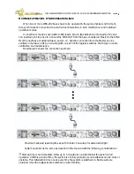
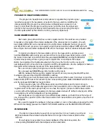
INTERCOM LINE TERMINAL IMPEDANCE SWITCH
The intercom lines should have a terminal impedance to make the different units
connected to them work correctly, however only one can connect a terminal impedance for
line because if they are connected two in parallel, the impedance would diminish in a half;
for this and in order to connect other units with a terminal impedance, it is possible to open
the terminal impedance placed at the base station. If the base station will be work in slave
mode with an intercom master station EF-200, keep in mind that you must leave the WBS-202
intercom line terminal impedance.
Each intercom line has its own intercom line terminal impedance switch placed at the rear
panel of the unit.
With the switch pressed the intercom line terminal impedance is in off mode and with the
switch depressed it is in on mode.
CAUTION:
Never leave the intercom line without terminal impedance, because a bad operation of
the units connected to the line would take place.
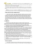
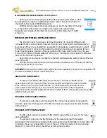
LINES A AND B LINK SWITCH
The lines A and B link switch allows to join the two channels, so that the same
signal appears in both channels. If the channels A and B are linked, the units connected
to the channel A can communicate with the one connected to the channel B and vice
versa, and the calls carried out in any channel will arrive to all the units connected to
both channels. The wireless beltpacks remain connected to their corresponding line though this
switch remain pressed .
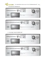
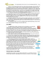
PROGRAM OUTPUT GAIN CONTROL
The program output gain control placed at the unit rear panel allows to regulate the
program signal level that appears in the XLR-3-32 male pa output connector placed at the
unit rear panel.
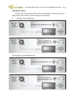
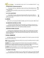
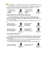
PROGRAM OUTPUT SIGNAL SELECT
The PA output signal is selected with this switch placed at the rear panel of the base
station WBS-202.
The program output can be the MIC signal of the base station (with this switch
depressed) or the line signal selected with the radio audio signal to A/B intercom line switch. It is
possible to choose an unique intercom line or the sum of the two intercom lines via internal
jumpers. For more information consult the special operation section.
WB-200 SERIES INTERCOM SYSTEM — WBS-202 DUAL CHANNEL WIRELESS BASE STATION

