ELite 5, User Manual
Page 28 of 159
Inside the ‘ELite 5’ Analyzer
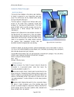
4.2.4 Front Panel
The touch screen display is the primary user interface
of ‘ELite 5’ analyzer for user interactions and data
entry. The LCD screen can be cleaned with a damp
sponge and gentle detergent.
The front panel is a hinged cover that provides easy
access to the shear valve, sampling needle and
syringes for cleaning and maintenance. The front
panel, START button, and the sample rotor can be
cleaned with a damp sponge and ethanol or
isopropanol.
Sample tube is placed into a tube adapter inserted on
the sample rotor for closed vial or open vial single-
tube manual sample processing. The sample tube is
rotated from the front of the unit into the inside of the
‘ELite 5’ for aspiration. This safety feature protects
the operator from inadvertent contact with the
aspiration needle during specimen processing.
Automatic sample processing with the optional Autosampler can be interrupted in order to
run one or more stat samples with the sample rotor. Automatic processing can be resumed
after stat sample processing is complete.
The START button allows easy one-hand operation of the ‘ELite 5’ analyzer. The color of the
START button indicates the status of the ‘ELite 5’ analyzer:
Green - ready to process samples
Red – busy
Orange - standby mode.
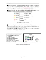
4.2.5 Back Panel
Power connector: the ‘ELite 5’ power connector should be
connected to a grounded power outlet that meets the
requirements listed in section 1.5.
Main power switch: this is a small switch located next to the
power connector. This switch turns off all electrical power to the
‘ELite 5’ analyzer. Leaving this switch on allows the ‘ELite 5’ to
remain in the standby mode. The switch is on when it is in the
‘up’ position labeled ‘1’ and is off when it is in the down position
labeled ‘0’.
Standby switch: flipping this switch to the ‘up’ position takes
the ‘ELite 5’ main computer out of the standby state and
powers up internal analyzer components. Please note that this
switch springs back to the down position when released and
does not stay in the ‘up’ position.
Figure 10. Elite 5 Front Panel
1
2
3
4
5
6
Figure 11. ELite 5 Back Panel
Start button
Touch screen
Sample rotor
Place for
autosampler
Summary of Contents for ELite 5
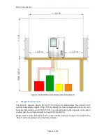
Page 13: ...ELite 5 User Manual Page 13 of 159 Figure 1 ELite 5 with Autosampler Space Requirements...
Page 27: ...ELite 5 User Manual Page 27 of 159 Figure 9 4DIFF Scatter Diagram...
Page 142: ...ELite 5 User Manual Page 142 of 159 20 3 Printed Report Formats...
Page 143: ...ELite 5 User Manual Page 143 of 159...
Page 153: ...ELite 5 User Manual Page 153 of 159 20 5 Fluidic System...

