background image

20

Vibration total value a

h,W

3.5 m/s

2

Uncertainty K

:

1.5 m/s

2

Rating label explanation

EBJ860 = Model number

E = Erbauer

BJ = Biscuit jointer

860= Power (Watts)

860 W Biscuit joiner_MNL_EBJ860_TPS_GB_V1_V20518_20180605.indd   20

6/5/18   9:04 AM

1. The vibration emission during actual use of the power tool can differ from the 

declared total value depending on the ways in which the tool is used; 

2. Need to identify safety measures to protect the operator that are based on an 

estimation of exposure in the actual conditions of use (taking account of all parts of the 

operating cycle such as the times when the tool is switched off and when it is running 

idle in addition to the trigger time).

Summary of Contents for 3663602795308

Page 1: ...EBJ860 EAN 3663602795308 ORIGINAL INSTRUCTIONS 860 W Biscuit joiner_MNL_EBJ860_TPS_GB_V2_BX220IM 10 8 2020...

Page 2: ...fety instructions 7 Product description 18 Assembly 21 Use 24 Care maintenance 27 Guarantee 30 Declaration of conformity 31 860 W Biscuit joiner_MNL_EBJ860_TPS_GB_V1_V20518_20180605 indd 2 6 5 18 9 03...

Page 3: ...1 x1 WARNING Please read all safety warnings carefully and be sure that they are fully understood before handling the tool 860 W Biscuit joiner_MNL_EBJ860_TPS_GB_V1_V20518_20180605 indd 3 6 5 18 9 03...

Page 4: ...4 Product description 1 1 2 3 4 5 6 7 8 16 15 14 13 12 11 10 9 17 18 19 860 W Biscuit joiner_MNL_EBJ860_TPS_GB_V1_V20518_20180605 indd 4 6 5 18 9 03 AM...

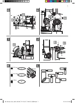
Page 5: ...5 A 5 B 2 C D 12 17 21 20 12 20 E F 16 18 16 18 19 860 W Biscuit joiner_MNL_EBJ860_TPS_GB_V1_V20518_20180605 indd 5 6 5 18 9 03 AM...

Page 6: ...6 G 1 2 3 22 15 14 H 2 1 3 9 10 I J 2 1 3 8 6 1 2 3 K L 8 12 mm 0 10 20 25 mm 12 15 mm 15 mm 860 W Biscuit joiner_MNL_EBJ860_TPS_GB_V1_V20518_20180605 indd 6 6 5 18 9 03 AM...

Page 7: ...ell lit Cluttered or dark areas invite accidents b Do not operate power tools in explosive atmospheres such as in the presence of flammable liquids gases or dust Power tools create sparks which may ig...

Page 8: ...current device RCD protected supply Use of an RCD reduces the risk of electric shock 3 PERSONAL SAFETY a Stay alert watch what you are doing and use common sense when operating a power tool Do not us...

Page 9: ...AND CARE a Do not force the power tool Use the correct power tool for your application The correct power tool will do the job better and safer at the rate for which it was designed b Do not use the po...

Page 10: ...ferent from those intended could result in a hazardous situation 5 SERVICE a Have your power tool serviced by a qualified repair person using only identical replacement parts This will ensure that the...

Page 11: ...The jointer bit can become damaged and lead to increased vibrations f Do not use blunt or damaged jointer blades Blunt or damaged jointer blades cause increased friction can become jammed and lead to...

Page 12: ...2012 now also targets to reduce the risks associated with silica wood and gypsum dusts Construction workers are one of the at risk groups within this because of the dust that they breathe silica dust...

Page 13: ...you can breathe after the right controls have been used How to reduce the amount of dust 1 Reduce the amount of cutting by using the best sizes of building products 2 Use a less powerful tool e g a b...

Page 14: ...ter microscopic particles VIBRATION The European Physical Agents Vibration Directive has been brought in to help reduce hand arm vibration syndrome injuries to power tool users The directive requires...

Page 15: ...the materials are grinded cut or drilled If the tool is in good condition and well maintained Use correct accessory for the tool and ensure it is sharp and in good condition The tightness of the grip...

Page 16: ...s in temperatures of 10 C or less Plan your work schedule to spread any high vibration tool use across a number of days HEALTH SURVEILLANCE All employees should be part of an employer s health surveil...

Page 17: ...uch as carpal tunnel syndrome To reduce this risk when using the product always wear protective gloves and keep your hands warm RESIDUAL RISKS Even if you are operating this product in accordance with...

Page 18: ...2 Spindle locking button 3 On off switch 4 Main handle 5 Base plate 6 Angle clamping knob 7 Saw blade guard 8 Angle scale 9 Height scale 10 Height clamping knob 11 Angle stop 12 Saw blade 13 Depth sto...

Page 19: ...an evaluation method of conformity for these directives was done WEEE symbol Waste electrical products should not be disposed of with household waste Please recycle where facilities exist Check with...

Page 20: ...vibration emission during actual use of the power tool can differ from the declared total value depending on the ways in which the tool is used 2 Need to identify safety measures to protect the opera...

Page 21: ...ve equipment WARNING The product must be fully assembled before operation Do not use a product that is only partly assembled or assembled with damaged parts Wear protective gloves for this assembly wo...

Page 22: ...he base plate Fig A Do not detach the four screws from the base plate 2 Press the spindle locking button 2 fully and hold it in position Fig B 3 Turn the outer flange 20 slightly with the spanner 17 u...

Page 23: ...ernal dust extraction device e g a suitable vacuum cleaner attachment 35 mm to the vacuum cleaner adaptor 18 and then attach to dust extraction outlet 16 Internal dust extraction with dust bag Fig F F...

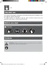
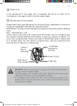
Page 24: ...asons it is essential to read the entire instruction manual before first operation and to observe all the instructions therein Before you start 01 Protection Controls WARNING Always switch the product...

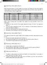
Page 25: ...trial cuts 4 Afterwards firmly tighten the lock nut 22 again Step 3 02 Adjusting cutting height Fig H The distance between the upper surface of the workpiece and the intended groove can be set 1 Loos...

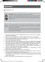
Page 26: ...ary Fig K 4 Set proper cutting height and angle 5 Never hold the workpiece with your hands or across your leg Secure the workpiece with proper clamps to a stable worktop Support longer workpieces to a...

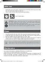
Page 27: ...hes and air vents after every use with a cloth and brush Remove stubborn dirt with high pressure air max 3 bar Check for worn or damaged parts Replace worn parts as necessary or contact an authorised...

Page 28: ...follows The wire which is coloured blue must be connected to the terminal which is marked with N or coloured black The wire which is coloured brown must be connected to the terminal which is marked L...

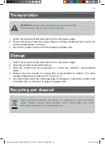
Page 29: ...s described above 3 Store the product and its accessories in a dark dry frost free well ventilated place 4 Always store the product in a place that is inaccessible to children The ideal storage temper...

Page 30: ...ects and damage caused by or resulting from Normal wear and tear Overload misuse or neglect Repairs attempted by anyone other than an authorised agent Cosmetic damage Damage caused by foreign objects...

Page 31: ...rective References to the following harmonized standard were made EN 60745 1 2009 A11 2010 EN 60745 2 19 2009 A1 2010 2014 30 EU Electromagnetic Compatibility directive References to the following har...

Page 32: ...Directive References to the following harmonized standard were made EN 60745 1 2009 A11 2010 EN 60745 2 19 2009 A1 2010 2014 30 EU Electromagnetic Compatibility directive References to the following h...

Page 33: ......

Page 34: ......

Page 35: ......

Page 36: ...3 Sheldon Square London W2 6PX United Kingdom www kingfisher com products Kingfisher International Products B V Rapenburgerstraat 175E 1011 VM Amsterdam The Netherlands Distributor www diy com www sc...

Reviews: