background image

29

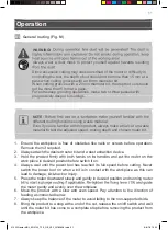
6.  Lower the motor housing slowly by applying pressure on both main handles (1) 

until the router bit touches the surface of the workpiece. Hold both main handles 

(1) in position and lock the fixing lever (19) with the finger of the left hand.

7.  Ensure that depth stop (7) stands on the step buffer (10) correctly and read the 

indicated value on the scale (7a). Reduce the desired cutting depth to the read 

value and lift the depth stop (7) accordingly.

8.  Tighten the fixing screw for depth stop (8) to fix the depth stop (7) in position.

EXAMPLE! 

The  indicated  value  is  60  mm  (6  on  the  scale  (7a)),  the 

desired cutting depth 5 mm. The target setting value is 55 mm. Pull the 

depth stop (7) upward until 55 mm is indicated.

NOTE: 

It is recommended to perform a trial cut in a piece of test wood to 

double check the cutting depth.

Fine adjustment (Fig. J, L)

Use the adjustment knob (3) for precise setting of cutting depth. The adjustment can 

be done both in locking and releasing position of fixing lever (19).

Turning of adjustment knob (3) can perform fine adjustment of cutting depth according 

following information:

1 mark on scale wheel (2) = 0.1 mm

1 turn of scale wheel (2) = 2.0 mm

1 mark on the scale (17) = 8 mm

Total adjustment range = 0-16 mm

1.  Align  the  “0”  mark  on  the  scale  wheel  (2)  with  the  fixed  indicator  on  the  motor 

housing by turning the scale wheel (2) without touching the adjustment knob (3).

2.  Rotate adjustment knob (3) clockwise to increase the cutting depth while the scale 

wheel (2) turns with the adjustment knob (3) synchronously.

3.  Rotate adjustment knob (3) anticlockwise to decrease the cutting depth while the 

scale wheel (2) turns with the adjustment knob (3) synchronously.

NOTE: 

After setting the cutting depth, the position of the reset-mark on 

the depth stop should not be changed any more so that the currently 

adjusted setting can always be read off the scale.

2100W router MNL_ER2100_TPS_GB_V02_20180608.indd   29

6/8/18   19:22

Summary of Contents for ER2100

Page 1: ...ER2100 EAN 3663602796299 ORIGINAL INSTRUCTIONS V20518 2100W router MNL_ER2100_TPS_GB_V02_20180608 indd 1 6 8 18 19 22...

Page 2: ...2 Safety instructions 8 Product description 18 Assembly 21 Use 27 Care maintenance 34 Guarantee 37 Declaration of conformity 38 2100W router MNL_ER2100_TPS_GB_V02_20180608 indd 2 6 8 18 19 22...

Page 3: ...3 1 x1 WARNING Please read all safety warnings carefully and be sure that they are fully understood before handling the tool 2100W router MNL_ER2100_TPS_GB_V02_20180608 indd 3 6 8 18 19 22...

Page 4: ...uct description 1 1 2 3 4 4 6 1 7 8 9 7a 10 9h 9a 9d 9e 9f 9g 9b 9c 11 13 14 12 5 16 15 20 13 19 23 24 25 26 27 22a 21c 21b 21a 22b 22c 18 17 2100W router MNL_ER2100_TPS_GB_V02_20180608 indd 4 6 8 18...

Page 5: ...5 A 3 2 1 23 20 14 B 9h 9a 9b 9b 9d 9d 9f 9g 9e 3 2 1 C D 3 2 1 13 11 9b 9b 9a 9h 9d 9e 21 9d 2 3 3 1 2 E F 2 1 3 9e R 9h 13 24 11 25 26 2100W router MNL_ER2100_TPS_GB_V02_20180608 indd 5 6 8 18 19 22...

Page 6: ...6 G 2 1 12 H 1 2 15 I J 6 18 19 3 2 1 K L 8 7 10 3 2100W router MNL_ER2100_TPS_GB_V02_20180608 indd 6 6 8 18 19 22...

Page 7: ...7 M N O P 25 26 A B 2100W router MNL_ER2100_TPS_GB_V02_20180608 indd 7 6 8 18 19 22...

Page 8: ...SAFETY a Keep work area clean and well lit Cluttered or dark areas invite accidents b Do not operate power tools in explosive atmospheres such as in the presence of flammable liquids gases or dust Pow...

Page 9: ...residual current device RCD protected supply Use of an RCD reduces the risk of electric shock 3 PERSONAL SAFETY a Stay alert watch what you are doing and use common sense when operating a power tool...

Page 10: ...correct power tool will do the job better and safer at the rate for which it was designed b Do not use the power tool if the switch does not turn it on and off Any power tool that cannot be controlle...

Page 11: ...ent or binding of moving parts breakage of parts and any other condition that may affect the power tool s operation If damaged have the power tool repaired before use Many accidents are caused by poor...

Page 12: ...kback k Turn the product off immediately if the router bit gets jammed l Never touch the workpiece with your hand when you are working on it m Keep the handles dry to ensure safe control Grip the prod...

Page 13: ...spirable Crystalline Silica or RCS during many common tasks such as cutting drilling and grinding Breathing in very fine particles of crystalline silica can lead to the development of lung cancer Sili...

Page 14: ...www hse gov uk pubns cis69 pdf WARNING Some dust particles created by power sanding sawing grinding drill and other construction jobs contain chemicals known to cause cancer birth defects or other rep...

Page 15: ...ue has been measured in accordance with EN 60745 1 and EN 60745 2 17 and may be used for compare one tool with another The declared vibration total value may also be used in a preliminary assessment o...

Page 16: ...your work schedule to spread any high vibration tool use across a number of days HEALTH SURVEILLANCE All employees should be part of an employer s health surveillance scheme to help identity any vibr...

Page 17: ...e with all the safety requirements potential risks of injury and damage remain The following dangers can arise in connection with the structure and design of this product 1 Health defects resulting fr...

Page 18: ...ob h Guide rods 10 Step buffer 11 Base plate 12 Vacuum cleaner adaptor 13 14 Spindle lock 15 On off switch 16 Lock off button 17 Scale 18 Indicator 19 Fixing lever for cutting depth adjustment 20 Clam...

Page 19: ...product off and disconnect it from the power supply before assembly cleaning adjustments maintenance storage and transportation This product is of protection class II That means it is equipped with en...

Page 20: ...min 1 1 4 3 8 and 1 2 inch for UK 6 8 and 12mm for EU 60 mm II Approx 4 kg 90 dB A 101 dB A 3 dB A 2 543 m s2 1 5 m s2 The sound emission values have been obtained according to the noise test code giv...

Page 21: ...protective equipment WARNING The product must be fully assembled before operation Do not use a product that is only partly assembled or assembled with damaged parts Wear protective gloves for this ass...

Page 22: ...use a router bit with a shaft diameter that does not fit to the collet Router bits are sharp and hot after use Handle them with care Wear safety gloves when handling router bits to avoid injuries lik...

Page 23: ...re the router bit is properly attached and free of damage Removing Fig A 1 Put the router upside down with its standing feet 4 on a stable work bench 2 Press the spindle lock 14 and turn the clamp nut...

Page 24: ...ntation line cross channel for cutting 2 Prepare the rough setting of the distance between the router bit and parallel guide as instructed above inserting while the distance should be 1 3mm away from...

Page 25: ...he base plate 11 and insert it Fig E step 2 9 Slide the adjustment guide assembly 9e with centre pin 21 and guide rods 9h x2 in the rail of the base plate 11 to adjust to adjust the desired cutting ra...

Page 26: ...s product Dust can be harmful to health Only assemble the vacuum cleaner adaptor 12 when the router bit is removed Attaching 1 Latch the front edge of the vacuum cleaner adaptor 12 in the opening of t...

Page 27: ...hold it in position 2 Press the on off switch 15 to switch the product on 3 Release the on off switch 15 to switch the product off 02 Speed dial Fig I Adjust the maximum speed by using the speed dial...

Page 28: ...e the motor housing by the spring force of the two pillars to its highest position Fig J step 1 WARNING Be aware of the spring force in the pillars and put one hand on the top of the router when relea...

Page 29: ...b 3 for precise setting of cutting depth The adjustment can be done both in locking and releasing position of fixing lever 19 Turning of adjustment knob 3 can perform fine adjustment of cutting depth...

Page 30: ...2 Release the fixing lever 19 by turning clockwise and raise the motor housing by the spring force of the two pillars until highest position Fig J step 1 WARNING Be aware of the spring force in the pi...

Page 31: ...uter downward slowly and gently in desired position and running router the router gently and evenly over the workpiece 6 Move the product with a slow and even speed Pay attention to the direction of f...

Page 32: ...ing Parallel cuts and edging shall use the parallel guide assembly 9 provided 1 Set the cutting depth first 2 Attach the parallel guide assembly 9 to the product 3 Place the product on the workpiece w...

Page 33: ...pressure against the template during operation to ensure the template guide lies flat against the template edge WARNING Only use router bits which are smaller than the centre opening of the template...

Page 34: ...tubborn dirt with high pressure air max 3 bar Check for worn or damaged parts Replace worn parts as necessary or contact an authorised service centre for repair before using the product again Do not u...

Page 35: ...oured marking identifying the terminals in your plug proceed as follows The wire which is coloured blue must be connected to the terminal which is marked with N or coloured black The wire which is col...

Page 36: ...ly 2 Clean the product as described above 3 Store the product and its accessories in a dark dry frost free well ventilated place 4 Always store the product in a place that is inaccessible to children...

Page 37: ...over defects and damage caused by or resulting from Normal wear and tear Overload misuse or neglect Repairs attempted by anyone other than an authorised agent Cosmetic damage Damage caused by foreign...

Page 38: ...References to the following harmonized standard were made EN 60745 1 2009 A11 2010 EN 60745 2 17 2010 2014 30 EU Electromagnetic Compatibility directive References to the following harmonized standar...

Page 39: ...2100W router MNL_ER2100_TPS_GB_V02_20180608 indd 40 6 8 18 19 22...

Page 40: ...ternational Products Limited 3 Sheldon Square London W2 6PX United Kingdom www kingfisher com products Distributor B Q plc Chandlers Ford Hants SO53 3LE United Kingdom www diy com Screwfix Direct Limi...

Reviews: