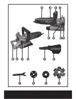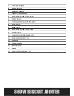
860W BISCUIT JOINTER
4. CUTTING GROOVE JOINTS (See Fig.7)
The various adjustments on the adjustable height
/ angle stop will enable you to make virtually any
biscuit joint imaginable. The tool may be further
enhanced by some simple jigs and fixtures that can
be easily made. Some of the more common biscuit
joinery applications are shown in Fig.7.
Note:
E:
EDGE TO EDGE JOINT
F:
EDGE MITRE JOINT
G:
OFFSET
H:
OFFSET JOINT
I:
CORNER JOINT
J:
“T” JOINT
K:
45
0
FRAME JOINT
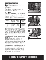
5. REPLACING THE CUTTING DISC (See Fig.8,
9)
Turn the machine around so that the base plate
faces upward.
Loosen the four screws (E) and remove the base
plate. Press the spindle lock button and keep it
pressed. Loosen and remove the outer flange with
the two-pin spanner. Take out the old cutting disc
and replace with a new one on the inner flange.
Important:
Make sure that the cutting direction of the teeth
(direction of the arrow on the disc) is visible and
corresponds with the direction of the arrow inside
of the base plate.
Position the outer flange back. With the spindle
lock button
(4)
pressed, tighten it with the spanner.
Note:
Make sure that the outer flange is placed in
correct side on the spindle.
Release the spindle lock and check if the
cutting disc is properly mounted and rotates
freely.
Place the base plate back and install the four
screws to tighten firmly.
Warning:
Make sure that the base plate is
locked securely before operation.
Fig. 1
Fig. 4
Fig. 3
A
Fig. 5
Fig. 8
Fig. 9
Fig. 7
Fig. 6
12
11
18
13
8
4
10
7
5
6
B
C
D
E
Fig. 2
Summary of Contents for ERB372BJC
Page 1: ...860W BISCUIT JOINTER ERB372BJC...
Page 2: ...Original Instructions Version 2 0...
Page 12: ...3 5 4 2 6 7 8 9 10 11 12 13 18 14 1 15 16 17...
Page 21: ......
Page 22: ......

