background image


DRUCKLUFT-NIBBLER


MONTAGE 

1. Entfernen Sie die Schutzkappe vom 

Luftanschluss (C). (Siehe Abb. 1) 


2. Befestigen Sie einen Stecker von Hand im 

Luftanschluss (C). (Siehe Abb. 2) 

HINWEIS: 

Verwenden Sie ein 

Gewindedichtungsband  


(nicht im Lieferumfang 

enthalten) am Stecker und ziehen Sie 
ihn mit einem Schraubenschlüssel 
luftdicht fest. ZiehenSienichtzusehr fest.  


3. Geben Sie 2

–3 Tropfen Öl für Druckluftwerk-

zeuge vor jedem Gebrauch in den Stecker. 
(Siehe Abb. 3) 

Summary of Contents for ERN647ATL-I

Page 1: ...AIR NIBBLER ERN647ATL I BX220IM ...

Page 2: ...upplied with this product are excluded from any guarantee offered This guarantee does not affect your statutory rights This guarantee is only valid in UK France Poland Germany Romania Spain Portugal and Ireland Congratulations on your purchase of a quality power tool from Kingfisher International Products B V This product should give you reliable service but for your peace of mind this power tool ...

Page 3: ...om the work area Keep children away Use of air tools 1 Stay alert and use common sense Watch what you are doing Do not operate the tool when you are tired or under the influence of alcohol drugs or medication 2 Do not overreach Keep proper footing and balance at all times 3 Always wear eye protectors which provides protection from flying particles from the front and side when using the tool Ear pr...

Page 4: ...e air inlet as they add weight and could fail due to vibration 22 This tool vibrates with use Continuous operation of this tool might be harmful to your hands or arms Stop using the tool if discomfort a tingling feeling or pain occurs Resume work after recovery Seek medical advice if a serious symptom occurs Air nibbler safety instructions 1 Always use the air nibbler in the manner and for the fun...

Page 5: ...rking pressure for the tool High pressure and unclean air will shorten the tool life due to the faster wear and also may create a safety hazard 6 Drain water from the air compressor tank daily as well as any condensation in the air lines Water in the air line may enter the tool and cause damage to the tool mechanisms at operation 7 Clean the tool air inlet screen filter for blockage weekly Clean i...

Page 6: ...thers the following symbols and abbreviations Familiarise yourself with them to reduce hazards like personal injuries and damage to property SPM Strokes per minute CFM Cubic feet per minute PSI Pound per square inch xxWxx Manufacturing date code year of manufacturing 20xx and week of manufacturing Wxx SN Serial number Caution Warning Read the instruction manual Wear hearing protection Wear eye pro...

Page 7: ...AIR NIBBLER PRODUCT DESCRIPTION ACCESSORY DESCRIPTION PART DESCRIPTION QUANTITY A Air Nibbler 1 B Trigger 1 C Air Inlet 1 D Die 2 E Blade 2 F Fixing Nut 1 E ...

Page 8: ...protect the operator that are based on an estimation of exposure in the actual conditions of use taking account of all parts of the operating cycle such as the times when the tool is switched off and when it is running idle in addition to the trigger time VIBRATION The European Physical Agents Vibration Directive has been brought in to help reducehand arm vibration syndrome injuries to power tool ...

Page 9: ...king period on this tool Helping to minimise your vibration exposure risk ALWAYS use qualified blades Maintain this tool in accordance with these instructions and keep well lubricated where appropriate Plan your work schedule to spread any high vibration tool use across a number of days Health Surveillance All employees should be part of an employer s health surveillance scheme to help identity an...

Page 10: ... the air inlet C See Figure 1 2 Mount the male plug by hand into the air inlet C See Figure 2 NOTE Use thread sealant tape not included on the male plug and tighten it with a wrench for airtight connection Do not overtighten 3 Place 2 3 drops of air tool oil into the male plug before each use See Figure 3 4 Connect air supply hose to the male plug See Figure 4 5 Set the working pressure at 90psi 6...

Page 11: ...ut NOTE This tool features an adjustable die which can be adjusted to the left or to the right direction Loosen the fixing nut F counterclockwise with a wrench not provided Turn the die D and blade E to the required direction to suit different applications of cuts Then tighten the die securely D See Figure 7 ...

Page 12: ...n the fixing nut F counterclockwise with a wrench not provided See Figure 8 3 Remove the die D by screwing it out counterclockwise with the wrench See Figure 9 4 Remove the blade base Part 34 with the blade E by screwing the blade base counterclockwise with the wrench See Figure 10 blade base ...

Page 13: ... the blade base Part 34 into position and tighten it secure with the wrench See Figure 12 7 Replace a new die D if necessary and screw it into position tight and secure with the wrench See Figure 13 8 Re tighten the fixing nut F securely with the wrench See Figure 14 blade base blade base ...

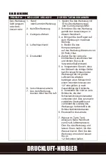
Page 14: ...ditional pressure drops and reduces the tool power Directly connect the hoses together 6 Replace rotor blade 7 Water in tank drain tank See air compressor manual Oil tool and run until no water is evident Oil tool again and run 1 2 seconds Abnormal vibration and or excessive heat develops in the tool Improper lubrication Follow proper lubrication procedures in this manual NOTE For any special trou...

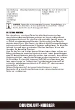
Page 15: ...s been evenly distributed throughout the tool The tool should be stored in a clean and dry environment Recommended lubricants use air tool oil or any other high grade turbine oil containing moisture absorbent rust inhibitors metal wetting agents and an EP extreme pressure additive Clean the tool all over with a cotton rag after each use Keep the tool in a dry and safe place out of reach of childre...

Page 16: ... blade 4 13 Rotor 1 14 Bolt 1 15 Cylinder 1 16 Front plate 1 17 Bearing 1 18 Spacer 1 19 Gear sleeve 1 Part No Description Qty 20 Gear 3 21 Pin 3 22 Gear seat 1 23 Fix ring 1 24 E clip 1 25 Bearing 2 26 Cushion 1 27 Bias axle 1 28 Rotating rod 1 29 Front housing 1 30 Lubrication cover 1 31 Bushing 1 32 Sliding shaft 1 33 Blade 1 34 Blade base 1 35 Die 1 36 Screw nut 1 37 Soft grip 1 ...

Page 17: ...itle Eric Capotummino Group Quality Director Kingfisher International Products B V Rapenburgerstraat 175E 1011 VM Amsterdam The Netherlands Authorised Signatory and technical file holder Date 09 10 2019 Signature We Importer Kingfisher International Products B V Rapenburgerstraat 175E 1011 VM Amsterdam The Netherlands AIR NIBBLER Customer Helpline Freephone UK 0800 324 7818 uk kingfisherservice co...

Page 18: ...ional Products Limited 3 Sheldon Square London W2 6PX United Kingdom EU Manufacturer Kingfisher International Products B V Rapenburgerstraat 175E 1011 VM Amsterdam The Netherlands www diy com www screwfix com To view instruction manuals online visit www kingfisher com products EN AIR NIBBLER ...

Page 19: ...AIR NIBBLER SÉ CATEUR PNEUMATIQUE ERN647ATL I de garantie 2ans ...

Page 20: ... Si votre produit présente un défaut pendant cette période vous devez dans un premier temps contacter le détaillant chez qui l article a été acheté Cette garantie exclut expressément les dommages causés par L usure normale Une utilisation inappropriée ou une négligence Un manque d entretien La défaillance d articles consommables tels que les batteries Les dommages accidentels Les dommages esthétiq...

Page 21: ...eptibles de représenter un risque s ils é taient endommagés suite àl utilisation de l outil 5 Maintenir les visiteurs àune distance de sécuritépar rapport àla zone de travail Tenir les enfants àl é cart Utilisation d outilspneumatiques 1 Rester vigilant et faire preuve de bon sens Rester attentif àla tâche en cours Ne pas utiliser l outil dans un é tat de fatigue ou sous l influence de drogues d a...

Page 22: ...l outil exécuter le travail àla vitesse pour laquelle il a étéconç u 19 Ne retirer aucune étiquette de l outil Les remplacer si elles sont illisibles ou endommagées 20 Toujours entretenir l outil avec soin Le garder propre pour garantir les meilleures performances en toute sécurité 21 Il est dé conseilléde placer les accouplements àchangement rapide directement au niveau de l admission d air car i...

Page 23: ... comprimépropre sec et ré gulé 2 Les compresseurs d air utilisé s avec l outil doivent se conformer aux directives de sécuritéapproprié es de la CommunautéEuropéenne 3 Vérifier que le compresseur d air utilisépour faire fonctionner l outil fournit la puissance d alimentation correcte CFM 4 Mettre l outil en position d arrêt avant de le raccorder àl alimentation d air 5 Utiliser une pression de fon...

Page 24: ...en air et le flexible 11 Vérifier avant chaque utilisation que les flexibles ne sont pas usé s S assurerquetoutes les connexions sontsécurisé es DISPOSITION DU CIRCUIT PNEUMATIQUE 1 Outilpneumatique 2 Flexible d air de 3 8 D I 3 Huileur 4 Régulateur de pression 5 Filtre 6 Vanned arrêt 7 Flexible de raccordement 8 Corps de coupleur et connecteur 9 Vidangerquotidiennement 10 Tuyau de 1 2 ou plus et ...

Page 25: ...nute CFM Cubic feet per minute pieds cubes par minute PSI Pound per square inch livre force par poucecarré xxWxx Code de date de fabrication année de fabrication 20xx et semaine de fabrication Wxx NS Numéro de série Attention Mise en garde Lire le manueld instructions Porter une protection auditive Porter une protection oculaire Porter des gants de protection Le produit est conforme aux directives...

Page 26: ...SÉ CATEUR PNEUMATIQUE DESCRIPTION DU PRODUIT DESCRIPTION DE L ACCESSOIRE PIÈCE DESCRIPTION QUANTITÉ A Sécateurpneumatique 1 B Déclencheur 1 C Admission d air 1 D Moule 2 E Lame 2 F Écrou de fixation 1 E ...

Page 27: ...ne estimation de l exposition dans des conditions réelles d utilisation en tenant compte de toutes les parties du cycle de fonctionnement par exemple lorsque l outil est éteint lorsqu il fonctionne en mode ralenti en plus du temps de déclenchement VIBRATION La directive europé enne sur les agents physiques vibrations a é téintroduite pour ré duire les blessures dues au syndrome des vibrations main...

Page 28: ...RS utiliser des lames autorisé es Entretenir cet outil conformément àces instructions et le conserver bien lubrifié le cas é ché ant Planifier les emplois du temps pour ré partir toute utilisation d un outil àfortes vibrations sur un certain nombre de jours Surveillance médicale Tous les employé s doivent suivre un programme de surveillance médicale de l employeur pour permettre d identifier àun s...

Page 29: ...omplet et exempt de tout dommage S il s avère que certaines pièces sont manquantes ou endommagées ne pas utiliser le produit et contacter votre concessionnaire 4 L utilisation d un produit incomplet ou endommagérepré sente un danger pour les personnes et les biens 5 S assurer que vous disposez de tous les accessoires et outils nécessaires pour le montage et le fonctionnement Celainclutégalementuné...

Page 30: ...ain dans l admission d air C Voir Figure 2 REMARQUE appliquer du ruban d étanchéitépour filetages non fourni sur le bouchon mâ le et le serrer avec une cléafin d obtenir un raccordement hermé tique Ne pas trop serrer 3 Appliquer 2 ou 3 gouttes d huile pour outil pneumatique dans le bouchon mâle avant chaque utilisation Voir Figure 3 ...

Page 31: ...igure 5 2 Maintenir fermement l outil A et approcher le côtéouvert du moule D de la piè ce àcouper Pousser l outil vers l avant le long de la piè ce àtravailler avec une force normale de la main Voir Figure 6 REMARQUE le côtéouvert du moule D doit être àl horizontale et dans l alignement de la pièce àcouper REMARQUE cet outil dispose d un moule ajustable qui peut être réglé vers la gauche ou vers ...

Page 32: ...xation F en le faisant tourner dans le sens antihoraire avec une clé non fournie Voir Figure 8 3 Déposer le moule D en le faisant tourner dans le sens antihoraire avec la clé Voir Figure 9 4 Déposer la base de la lame Référence 34 avec la lame E en faisant tourner la base de la lame dans le sens antihoraire avec la clé Voir Figure 10 Base de la lame ...

Page 33: ...11 6 Recaler la base de la lame ré férence 34 en position et la serrer fermement avec la clé Voir Figure 12 7 Si né cessaire poser un nouveau moule D et le visser fermement avec la clé Voir Figure 13 8 Resserrer fermement l écrou de fixation F avec la clé Voir Figure 14 Base de la lame Base de la lame ...

Page 34: ...Utiliser du rubanadhé sifd étanché ité 5 a S assurer que le flexible est de la bonne taille Un flexible long ou des outils utilisant de grandes quantités d air peuvent nécessiter un flexible de 1 2 in de diamètre ou plus en fonction de la longueur totale des flexibles b Ne pas utiliser plusieurs flexibles branchés ensemble avec des raccords rapides Cela provoque une chute de pression supplémentair...

Page 35: ...aisseur en ligne est correctement réglélorsqu une petite quantités accumule sur le papier Une quantitéexcessive d huile doit être évité e Dans le cas oùil s avèrerait né cessaire de stocker l outil pour une période prolongée il doit alors être lubrifiégé néreusement Faire tourner l outil pendant environ 30 secondes pour s assurer que l huile a étérépartie uniformément dans l ensemble de l outil L ...

Page 36: ... 1 12 Lame de rotor 4 13 Rotor 1 14 Boulon 1 15 Cylindre 1 16 Plaque avant 1 17 Roulement 1 18 Entretoise 1 19 Manchon de pignon 1 Réf Description Qté 20 Pignon 3 21 Broche 3 22 Siège du pignon 1 23 Anneau fixe 1 24 Attache en E 1 25 Roulement 2 26 Coussin 1 27 Axe de polarisation 1 28 Tige de rotation 1 29 Carter avant 1 30 Couvercle de lubrification 1 31 Bague 1 32 Arbrecoulissant 1 33 Lame 1 34...

Page 37: ...Description Sécateur pneumatique Model ERN647ATL I Nom Titre Eric Capotummino Group Quality Director Kingfisher International Products B V Rapenburgerstraat 175E 1011 VM Amsterdam The Netherlands Authorised Signatory and technical file holder Date 09 10 2019 Signature We Importer Kingfisher International Products B V Rapenburgerstraat 175E 1011 VM Amsterdam The Netherlands SÉ CATEUR PNEUMATIQUE ...

Page 38: ...Sheldon Square London W2 6PX United Kingdom EU Manufacturer Kingfisher International Products B V Rapenburgerstraat 175E 1011 VM Amsterdam The Netherlands www castorama fr www bricodepot fr Pour consulter les manuels d instructions en ligne rendez vous sur le site www kingfisher com products FR SÉ CATEUR PNEUMATIQUE ...

Page 39: ...PNEUMATYCZNE NOŻYCE WIBRACYJNE ERN647ATL I gwarancji 2lata ...

Page 40: ...czonych z urządzeniem Niniejsza gwarancja nie wpływa na prawa użytkownika wynikające z obowiązujących przepisów Niniejsza gwarancja obowiązuje wyłącznie w Wielkiej Brytanii Francji Polsce Niemczech Rumunii Hiszpanii Portugalii i Irlandii Gratulujemy zakupu wysokiej jakości narzędzia firmy Kingfisher International Products B V Narzędzie powinno charakteryzować się odpowiednią niezawodnością jednak ...

Page 41: ...enia przez narzędzie mogłyby spowodować zagrożenie 5 Osoby postronne muszą zachować bezpieczną odległość od miejsca pracy Nie zezwalać aby w pobliżuprzebywałydzieci Użytkowanienarzędzipneumatycznych 1 Zachowywać ostrożność i rozsądek Zwracać uwagę na wykonywane czynności Nie obsługiwać narzędzia w stanie zmęczenia lub też pod wpływem narkotyków alkoholu bądź leków 2 Nie sięgać zbyt daleko Zawsze z...

Page 42: ...hniczny narzędzia Utrzymywać narzędzie w czystości aby zapewnić jego optymalną wydajność i bezpieczeństwo 21 Niezalecane jest umieszczanie szybkozłączek bezpośrednio na wlocie powietrza ponieważ powoduje to zwiększenie wagi i może skutkować uszkodzeniem w wyniku drgań 22 Narzędzie drga podczas pracy Ciągłe użytkowanie narzędzia może być szkodliwe dla dłoni i ramion W przypadku poczucia dyskomfortu...

Page 43: ... powietrza pochodzącego z regulowanego źródła 2 Sprężarki powietrza stosowane z tym narzędziem muszą być zgodne z odpowiednimi dyrektywami bezpieczeństwa Wspólnoty Europejskiej 3 Upewnić się że sprężarka powietrza używana do zasilania narzędzia zapewnia odpowiedni wydatek 4 Wyłączyć narzędzie przed podłączeniem go do źródła powietrza 5 Używać normalnego ciśnienia roboczego dla narzędzia wynosząceg...

Page 44: ... powietrza 11 Przed każdym użyciem sprawdzić stan węży Upewnić się że wszystkie połączenia są bezpieczne UKŁAD INSTALACJI PNEUMATYCZNEJ 1 Narzędziepneumatyczne 2 Wążpowietrza 3 8 średnicawewnętrzna 3 Olejarka 4 Regulator ciśnienia 5 Filtr 6 Zawórodcinający 7 Odcinekwęża 8 Korpuszłączkiizłącze 9 Spustcodzienny 10 Przewód i złącze 1 2 cala lub większe 11 Osuszaczpowietrza 12 Przewód i złącze 1 cal l...

Page 45: ...i uszkodzeń mienia SPM Liczbaskokównaminutę CFM Stopysześciennenaminutę PSI Funtynacalkwadratowy xxWx x Kod daty produkcji rok 20xx oraz tydzień Wxx produkcji SN Numerseryjny Przestroga ostrzeżenie Zapoznać się z instrukcją obsługi Stosowaćśrodkiochronysłuch u Stosowaćśrodkiochronywzrok u Stosowaćrękawiceochronne Produkt jest zgodny z odpowiednimi dyrektywami europejskimi oraz z zastosowaną metodą...

Page 46: ...PNEUMATYCZNE NOŻYCE WIBRACYJNE OPIS PRODUKTU OPIS AKCESORIÓ W CZĘŚĆ OPIS LICZBA A Pneumatycznenożycewibracyjne 1 B Spust 1 C Wlotpowietrza 1 D Uchwyt 2 E Ostrze 2 F Nakrętkamocująca 1 E ...

Page 47: ...ędzia W celu ochrony operatora należy stosować odpowiednie środki bezpieczeństwa na podstawie oceny narażenia na rzeczywiste warunki użytkowania z uwzględnieniem wszystkich elementów cyklu obsługi takich jak czas działania czas wyłączenia narzędzia oraz czas pracy jałowej DRGANIA Jako pomoc w ograniczeniu urazów związanych z chorobą wibracyjną u użytkowników narzędzi została opracowana europejska ...

Page 48: ...iejszą instrukcją i zapewnić jego prawidłowe smarowanie o ile jest to wymagane Zaplanować pracę aby rozłożyć korzystanie z narzędzi powodujących silne drgania na wiele dni Kontrola zdrowia Wszyscy pracownicy powinni uczestniczyć w prowadzonym przez pracodawcę programie kontroli zdrowia który pozwala diagnozować choroby związane z drganiami na wczesnym etapie i zapobiegać postępowaniu choroby a tak...

Page 49: ...tość opakowania jest kompletna i nieuszkodzona W przypadku stwierdzenia braku lub uszkodzenia jakichkolwiek elementów nie korzystać z produktu lecz skontaktować się ze sprzedawcą 4 Korzystanie z niekompletnego lub uszkodzonego produktu stwarza zagrożenie dla ludzi i mienia 5 Upewnić się że dostępne są wszystkie akcesoria i narzędzia wymagane do montażu i użytkowania Obejmuje to równieżodpowiednieś...

Page 50: ... złącze męskie na wlocie powietrza C Patrzrys 2 UWAGA nawinąć na złącze męskie taśmę do uszczelniania gwintów brak w zestawie a następnie dokręcić je kluczem aby zapewnić szczelność połączenia Niedokręcaćzezbytdużąsiłą 3 Przed każdym użyciem wpuścić do złącza męskiego 2 3 krople oleju do narzędzi pneumatycznych Patrzrys 3 ...

Page 51: ... Patrzrys 5 2 Silnie przytrzymać narzędzie A i zbliżyć otwartą część uchwytu D do ciętego elementu Przesuwać narzędzie wzdłuż ciętego elementu stosując umiarkowaną siłę nacisku Patrz rys 6 UWAGA otwarta część uchwytu D powinna być ustawiona poziomo i równo z ciętym elementem UWAGA narzędzie ma regulowany uchwyt który można przestawić w lewo lub w prawo Poluzować nakrętkę mocującą F obracając ją w ...

Page 52: ... Patrzrys 8 2 Poluzować nakrętkę mocującą F obracając ją w lewo przy użyciu klucza brak w zestawie Patrzrys 8 3 Wykręcić uchwyt D obracając go w lewo przy użyciu klucza Patrzrys 9 4 Wymontować podstawę ostrza część nr 34 wraz z ostrzem E obracając ją w lewo przy użyciu klucza Patrzrys 10 podstawaostrza ...

Page 53: ... 6 Zamontować podstawę ostrza część nr 34 w odpowiednim miejscu a następnie dokręcić ją przy użyciu klucza Patrzrys 12 7 W razie potrzeby zamontować nowy uchwyt D i przykręcić go przy użyciu klucza Patrzrys 13 8 Dokręcić nakrętkę mocującą F przy użyciu klucza Patrzrys 14 podstawaos trza podstawaostrza ...

Page 54: ...zczelności należy zacisnąć i uszczelnić elementy połączeniowe węży Użyćtaśmyuszczelniającej 5 a Użyć węża o odpowiednich wymiarach W przypadku dłuższych węży lub narzędzi wymagających większej ilości powietrza może być wymagane zastosowanie węża o średnicy wewnętrznej 1 2 cala lub większej w zależności od całkowitej długości węży b Nie używać wielu węży połączonych razem przy użyciu szybkozłączek ...

Page 55: ...0 sekund Przy prawidłowym ustawieniu olejarki szeregowej na papierze powinna się pojawić niewielka plama oleju Należy unikać nadmiernych ilości oleju Jeśli wymagane jest dłuższe przechowywanie narzędzia należy je odpowiednio nasmarować Narzędzie powinno pracować przez około 30 sekund aby zapewnić odpowiednie rozprowadzenie oleju Wymagane jest przechowywanie narzędzia w czystym i suchym miejscu Zal...

Page 56: ...ka 4 13 Wirnik 1 14 Śruba 1 15 Cylinder 1 16 Płytkaprzednia 1 17 Łożysko 1 18 Element dystansowy 1 19 Tulejaprzekładni 1 Nr części Opis Liczba 20 Kołazębate 3 21 Trzpień 3 22 Gniazdoprzekładni 1 23 Pierścieńmocujący 1 24 Zacisk 1 25 Łożysko 2 26 Element tłumiący 1 27 Ośmimośrodowa 1 28 Element obrotowy 1 29 Obudowaprzednia 1 30 Korekzespołusmarowania 1 31 Tuleja 1 32 Wałekślizgowy 1 33 Ostrze 1 34...

Page 57: ...ucts B V Rapenburgerstraat 175E 1011 VM Amsterdam The Netherlands deklarujemy że produkt opis pneumatyczne nożyce wibracyjne model ERN647ATL I Nazwisko stanowisko Eric Capotummino Group Quality Director Kingfisher International Products B V Rapenburgerstraat 175E 1011 VM Amsterdam The Netherlands Upoważniony sygnatariusz i posiadacz dokumentacji technicznej Date 09 10 2019 Podpis PNEUMATYCZNE NOŻY...

Page 58: ...s Limited 3 Sheldon Square London W2 6PX United Kingdom EU Manufacturer Kingfisher International Products B V Rapenburgerstraat 175E 1011 VM Amsterdam The Netherlands www castorama pl Aby zapoznać się z instrukcją obsługi online odwiedź stronę www kingfisher com products PL PNEUMATYCZNE NOŻYCE WIBRACYJNE ...

Page 59: ...DRUCKLUFT NIBBLER ERN647ATL I Garantie 2Jahre ...

Page 60: ...ind von der Garantie ausgeschlossen Ihre gesetzlichen Ansprüche bleiben von dieser Garantie unberührt Diese Garantie gilt nur in Großbritannien Frankreich Polen Deutschland Rumänien Spanien Portugal und Irland GARANTIE Herzlichen Glückwunsch zum Kauf eines Qualitäts Elektrowerkzeugs von Kingfisher International Products B V Sie haben ein zuverlässiges Produkt erworben Zu Ihrer Sicherheit gilt für ...

Page 61: ...erfläche befindet 4 Vergewissern Sie sich dass keine Stromkabel Gasleitungen usw vorhanden sind die bei einer Beschä digung durch das Werkzeug eine Gefä hrdung darstellen können 5 Sorgen Sie dafür dass alle Besucher den Sicherheitsabstand zum Arbeitsbereich einhalten HaltenSie Kinder fern Verwendung von Druckluftwerkzeugen 1 Seien Sie wachsam und wenden Sie gesunden Menschenverstand an Achten Sie ...

Page 62: ... Werkzeugs von Hä nden und Körper fern 17 Tragen Sie das Werkzeug nicht am Luftschlauch 18 Üben Sie keinen übermä ßigen Druck auf das Werkzeug aus Lassen Sie das Werkzeug mit der Frequenz arbeiten für die es ausgelegt wurde 19 Entfernen Sie keine Etiketten vom Werkzeug Ersetzen Sie sie wenn Sie nicht mehr gut lesbar sind oder beschädigt wurden 20 Behandeln Sie das Werkzeug mit Sorgfalt Halten Sie ...

Page 63: ...n Bedienern auf LUFTZUFUHR Weitere Informationen entnehmen Sie dem üblichen unten empfohlenen Luftsystem WARNHINWEIS Druckluft kann gefährlich sein Machen Sie sich mit allen Vorsichtsmaßnahmen zum Gebrauch von Kompressoren und Druckluftversorgung vertraut 1 Verwenden Sie zur Stromversorgung nur saubere trockene geregelte Druckluft 2 Druckluftkompressoren die mit dem Werkzeug verwendet werden mü ss...

Page 64: ...u montieren da sie durch Schwingungen am Werkzeug während des Betriebs zu einer Störung führen können Verwenden Sie stattdessen einen Zwischenschlauch und montieren Sie die Kupplung zwischen Luftzufuhr und Schlauchpeitsche 11 Überprüfen Sie die Schläuche vor jedem Gebrauch auf Verschleiß Vergewissern Sie sich dass alle Verbindungen sicher sind AUFBAU LUFTSYSTEM 1 Druckluftwerkzeug 2 Luftschlauch 3...

Page 65: ...M Schlä ge pro Minute CFM Kubikfußpro Minute PSI Pfund pro Quadratzoll xxWxx Herstellungsdatumsschlü ssel Herstellungsjahr 20xx und Kalenderwoche der Produktion Wxx SN Seriennummer Vorsicht Warnhinweis LesenSie das Handbuch TragenSieeinenGehörschutz TragenSie eine Schutzbrille TragenSieSchutzhand schuhe Das Produkt entspricht den geltenden europäischen Normen und ein Verfahren zur Beurteilung der ...

Page 66: ...DRUCKLUFT NIBBLER PRODUKTBESCHREIBUNG ZUBEHÖ RBEZEICHNUNG TEIL BEZEICHNUNG MENGE A Druckluft Nibbler 1 B Auslö ser 1 C Luftanschluss 1 D Düse 2 E Blatt 2 F Feststellmutter 1 E ...

Page 67: ... Werkzeugs und je nach Sicherheitsmaßnahmen zum Schutz des Bedieners abweichen die auf einer geschätzten Gefährdung unter den gegenwärtigen Nutzungsbedingungen beruhen unter Berücksichtigung aller Elemente eines Betriebszyklus wie z B neben den Einschaltzeiten auch Zeiten in denen das Werkzeug ausgeschaltet ist und in denen es sich im Leerlauf befindet SCHWINGUNG Die europäische Richtlinie zum Sch...

Page 68: ...ise verwendet wird WARNHINWEIS Sicherheitsmaßnahmen die auf einer geschätzten Gefährdung unter den gegenwärtigen Nutzungsbedingungen beruhen unter Berücksichtigung aller Elemente eines Betriebszyklus wie neben den Einschaltzeiten auch Zeiten in denen das Werkzeug ausgeschaltet ist und in denen es sich im Leerlauf befindet dienen dem Schutz des Bedieners Hinweis dazu Arbeitet der Bediener zusätzlic...

Page 69: ... Inbetriebnahme zu lesen und die Anleitung zu beachten Dieses Gerät ist für den privaten Hausgebrauch und nicht fü r den gewerblichen Einsatz bestimmt Esdarfausschließlichfür die beschriebenenZweckeverwendetwerden AUSPACKEN 1 Packen Sie alle Teile aus und legen Sie sie auf eine ebene stabile Oberflä che 2 Entfernen Sie das gesamte Verpackungs und Versandmaterial 3 Vergewissern Sie sich dass die Li...

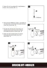
Page 70: ...er von Hand im Luftanschluss C Siehe Abb 2 HINWEIS Verwenden Sie ein Gewindedichtungsband nicht im Lieferumfang enthalten am Stecker und ziehen Sie ihn mit einem Schraubenschlü ssel luftdicht fest ZiehenSienichtzusehr fest 3 Geben Sie 2 3 Tropfen Öl für Druckluftwerk zeuge vor jedem Gebrauch in den Stecker Siehe Abb 3 ...

Page 71: ...bringen Sie die offene Seite der Düse D zum Werkstück das Sie bearbeiten wollen Bewegen Sie das Werkzeug mit normaler Handkraft entlang des Werkstü cks Siehe Abb 6 HINWEIS Die offene Seite der Düse D sollte horizontal und in einer Linie mit dem zu bearbeitenden Werkstück sein HINWEIS Das Werkzeug verfügt über eine einstellbare Dü se die in Rechts oder Linksrichtung eingestellt werden kann Lö sen S...

Page 72: ...schlü ssel nicht im Lieferumfang enthalten gegen den Uhrzeigersinn Siehe Abb 8 3 Entfernen Sie die Düse D indem Sie sie mit einem Schraubenschlüssel gegen den Uhrzeigersinn herausdrehen Siehe Abb 9 4 Entfernen Sie die Blattbasis Teilenr 34 zusammen mit dem Blatt E indem Sie die Blattbasis mit dem Schraubenschlüssel gegen den Uhrzeigersinn herausdrehen SieheAbbildung 10 ...

Page 73: ...lenr 34 wieder ein und ziehen Sie sie mit dem Schraubenschlüssel sicher fest Siehe Abb 12 7 Ersetzen Sie die Dü se D falls nötig und schrauben Sie sie fest und sicher mit dem Schraubenschlü ssel an Siehe Abb 13 8 Ziehen Sie die Feststellmutter F mit dem Schraubenschlü ssel wieder sicher fest Siehe Abb 14 Blattbasis Blattbasis ...

Page 74: ...Sie bei Lecks die Dichtschlauch anschlü sse fest und dichten Sie sie ab VerwendenSieDichtband 5 a Vergewissern Sie sich dass der Schlauch die richtige Grö ße hat Ein langer Schlauch oder Werkzeuge die mit großen Luftvolumina arbeiten benö tigen einen Schlauch mit einem Innendurchmesser von 1 2 oder grö ßer je nach Gesamtlä nge der Schlä uche b Verwenden Sie nicht zu viele Schlä uche die ü ber Schn...

Page 75: ... Nähe der Abluftöffnung des Werkzeugs anbringen und die Drosselklappe etwa 30 Sekunden geö ffnet lassen Der Inline Öler ist korrekt eingestellt wenn ein schwacher Ölfleck auf dem Papier sichtbar wird Vermeiden Sie ü bermäßige Ölmengen Wenn Sie das Werkzeug für einen längeren Zeitraum lagern müssen sollte es zum Zeitpunkt der Lagerung ausreichend geschmiert werden Lassen sie das Werkzeug etwa 30 Se...

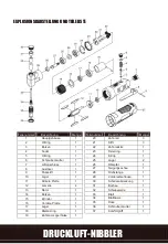
Page 76: ...atte 1 12 Lamelle 4 13 Rotor 1 14 Bolzen 1 15 Zylinder 1 16 Vordere Platte 1 17 Lager 1 18 Distanzring 1 19 Zahnrad Lagerhülse 1 Teilenummer Bezeichnung Menge 20 Zahnrad 3 21 Stift 3 22 Zahnradsitz 1 23 Fixierring 1 24 E Clip 1 25 Lager 2 26 Dämpfer 1 27 Neigungsachse 1 28 Drehstange 1 29 VorderesGehäuse 1 30 Schmierabdeckung 1 31 Buchse 1 32 Schiebewelle 1 33 Blatt 1 34 Blattbasis 1 35 Düse 1 36 ...

Page 77: ...tional Products B V Rapenburgerstraat 175E 1011 VM Amsterdam The Netherlands erklären dass das Gerät mit der Bezeichnung Druckluft nibbler Modell ERN647ATL I Befugter Unterzeichner und Inhaber der technischen Unterlagen Datum 09 10 2019 Unterschrift Name Titel Eric Capotummino Group Quality Director Kingfisher International Products B V Rapenburgerstraat 175E 1011 VM Amsterdam The Netherlands DRUC...

Page 78: ......

Reviews: