EG_GenLoc41e_1055_UG_003_UK
Page 19 / 71
Descriptions and non-contractual illustrations in this document are given as an indication only.
ERCOGENER reserves the right to make any modifications.
Dct_427_02
* contact us
5 Using the modem
5.1 Starting with the modem
5.1.1 Mounting the modem
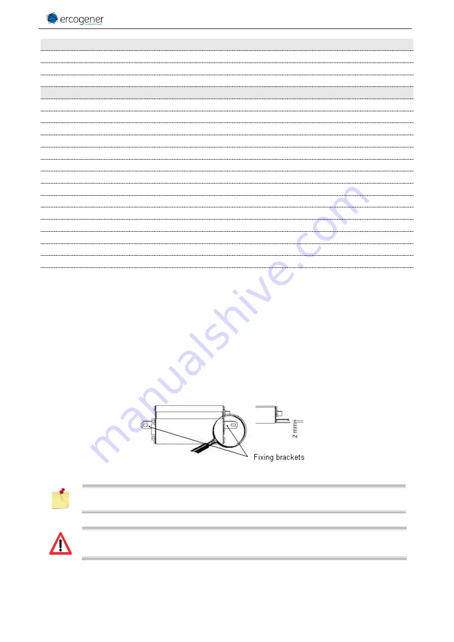
To mount the modem on a support, use the fixing brackets as described below.
The aluminum casing of the modem is connected to the 0V (GND) of the power supply and to
the 0V of the RS232 serial link. To avoid any risk of conduction of the ground plane to other
equipments,
the modem must be electrically insulated from its mechanical support.
Accessories supplied
- Fixing brackets (x2)
- 4-wire Micro FIT cables (Power supply, Input and Output)
- 2-wire Micro FIT cables (2 Inputs)
Options / Accessories *
- Back-up battery
- Management of battery charge
- Command ON/OFF of external supply by soft
- Command ON/OFF of external supply by DTR
- Power down of the RS232 by soft
- Backup Real Time Clock (if option backup battery)
- Bus I2C (instead of signals DSR and RTS)
- 3-axis accelerometer
- Analog input (instead of opto-coupled input E2)
- Analog input (instead of output SPKN)
- Gen 10400 : Adapter RS232 / Digital Tachograph
- GenBlue 15e : Adapter Bluetooth® / RS232 auto-supplied
- 1 port ONE_WIRE
- Software development kit : cdrom SDK EGM
- Accessories: Antennas, cables, power supply... (consult our website)
- Must be fixed on a flat surface.
- Max. height of the screw head : 2 mm.


