EG_GenLoc41e_1055_UG_003_UK
Page 40 / 71
Descriptions and non-contractual illustrations in this document are given as an indication only.
ERCOGENER reserves the right to make any modifications.
Dct_427_02
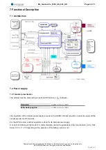
The available signals on the RS232 serial link are:
TX data (CT103/TX) : Data emission,
RX data (CT104/RX) : Data reception,
Request To Send (CT105/RTS) : Request to send,
Clear To Send (CT106/CTS) : Ready to send,
Data Terminal Ready (CT108-2/DTR) : Data terminal ready,
Data Set Ready (CT107/DSR) : Data set ready,
Data Carrier Detect (CT109/DCD) : Signal detection (optional) and Buzzer output (by default),
Ring Indicator (CT125/RI) / 3.8V : Call indicator (optional) and 3.8V power supply for GenBlue 15e or
Gen10400 (by default).
Normalized signals of a RS232 serial link
The RS232 interface was designed to allow a certain flexibility in the use of the serial interface signals. In
fact, after the setting (see command
AT+IFC
), the modem can work in 3-wire mode (using only the signals
TX, RX, GND), but the use of the signals TX, RX, GND, CTS, RTS is required for a GPRS application, which
is not the case for the signals DTR, DSR, DCD/Buzzer and RI/3.8V which may not be used.
7.3.2 Pins description
(1*) By default
Signal
Sub HD
connector
Pin N°
I/O
RS232
standar
d
Description
Added function
CTXD/CT103
2
I
TX
Transmit serial
data
CRXD/CT104
6
O
RX
Receive serial
data
CRTS/CT105
12
I
RTS
Request To Send
CCTS/CT106
11
O
CTS
Clear To Send
CDSR/CT107
7
O
DSR
Data Set Ready
Frames NMEA/UBX
Output clock I2C
(TWCK)
CDTR/CT108-2
8
I
DTR
Data Terminal
Ready
Frames UBX
Command
ON/OFF of
power supply
CDCD/CT109
1
O
DCD
Buzzer output (1*)
CRI/CT125
13
O
RI
Power supply 3.8V
(1*)
CT102/GND
9
Ground
Data signal I2C
(TWD)


