EG_GenPro400e_1103_UG_001_UK
Page 20 / 46
Descriptions and non-contractual illustrations in this document are given as an indication only.
ERCOGENER reserves the right to make any modifications.
Dct_427_02
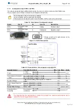
3.5 Serial link RS232C
The serial links RS232C and USB cannot work simultaneously.
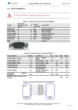
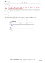
Table 13 : Description of pins of serial link RS232C
Signal
Connector
Sub-HD 15 pints
Pins N°
I/O
RS232
standards
Description
CT103 / TX
2
I
TX
Data transmission
CT104 / RX
6
O
RX
Data reception
CT107 / DSR
7
O
DSR
Data set ready
CT108-2 / DTR 8
I
DTR
Data terminal ready
CT106 / CTS
11
O
CTS
Ready to send
CT105 / RTS
12
I
RTS
Request to send
CT125 / RI
13
O
RI
Call indicator
GND
9
Ground
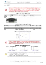
Table 14 : Characteristics of serial link RS232C
Characteristics
Symbols
Conditions
Min.
Typ.
Max.
Unité
Input Voltage
– Range
V
INPUT
Input
Voltage
–
Range
-25
+25
V
DC
Input Voltage
– Low
V
IL
Input Voltage
– Low
0.6
1.1
V
DC
Input Voltage
– High
V
IH
Input Voltage
– High
1.5
24
V
DC
Input Hysteresis
V
Hys
Input Hysteresis
0.5
V
DC
Input Resistance
R
in
Input Resistance
3
5
7
KΩ
Output Voltage
V
OUT
All transmitter
outputs loaded with
3 kΩ to ground
±5
±5.4
V
DC
Transmitter
Output
Resistance
R
OUT
300
50k
Ω
RS-232 Output Short-Circuit
Current
I
CC
±60
mA
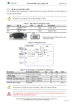
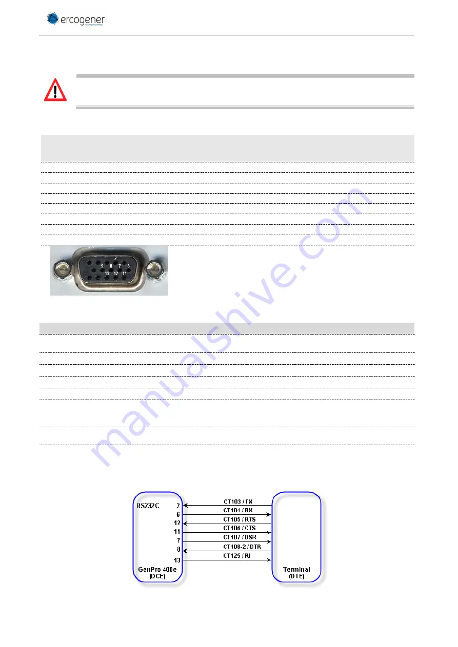
Figure 8 : Standards signals of serial link RS232C

