R U/L/H Series
User Guide, Rev. 00 (May 2015)
10
1.3.1.2
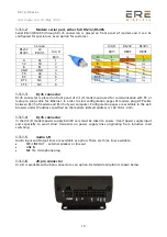
Modem serial port, either full RS232/RS485
Serial RS232/RS485 (through RJ-45 connector) is placed on front panel of modem and it can be
configured for special use as an option for customer.
Version
U/L/H
RS232
RS485
RS232
RS485
2x
RS485
U/L/H
RJ45
DB9F
DB9F
RJ45
A
1 nc 1
A A1 1
5V
2 2
2
5V 5V 2
B
3 3 nc
B B1 3
GND
4 nc nc
GND GND 4
TX
5 5 5
TX A2 5
RX
6 nc 6
RX B2 6
RTS
7 7 nc
RTS NC 7
CTS 8 8 nc
CTS
NC
8
1.3.1.3
RJ-45 connector
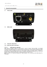
RJ-45 connector is placed on front panel of U/L/H modem and used for communication with PC or
laptop to plug cable for Ethernet. In order to start configuration pages of modem plug UTP cable
between RJ-45 of modem and RJ-45 of your computer. Configuration pages are available in the web
browser under IP address specified on the modem (default address is 192.168.1.234).
1.3.1.4
RJ-45 connector
In the U/L/H modem power supply 6V-30V care must be taken to ensure “clean” power supply input
and especially to avoid short transients on power supply lines originating from inductive load
switching.
1.3.1.5
Audio I/O
Audio Input and Output lines are available as option. There are three lines available:
SPK/LINE OUT – external speaker or line out
LINE IN
MIC IN –microphone plug
1.3.1.6
20-pin connector
U/L/H is available with 20pin connector as an option. Detailed description is shown below.


