SR2 Technical Manual EN
Indice : C
25/03/2019
Firmware v2.9
7 / 31
ERECA SAS - 75 rue d'Orgemont, 95210 St Gratien France
T : +33 1 39 89 76 23 W : www.ereca.fr
2.3 INTERFACES DESCRIPTION/ PORTS MODE
This section includes the pinout for all electrical access and describes protocol audio interfaces such as
MADI / SDI embedded Audio / Dante. For SDI, MADI and Ethernet the input process is also described in this
section in order to keep concise documentation.
2.3.1 General Purpose IN
For forward product compatibility the GP IN section is split on two kind of connectors.
Inputs 1 and 2
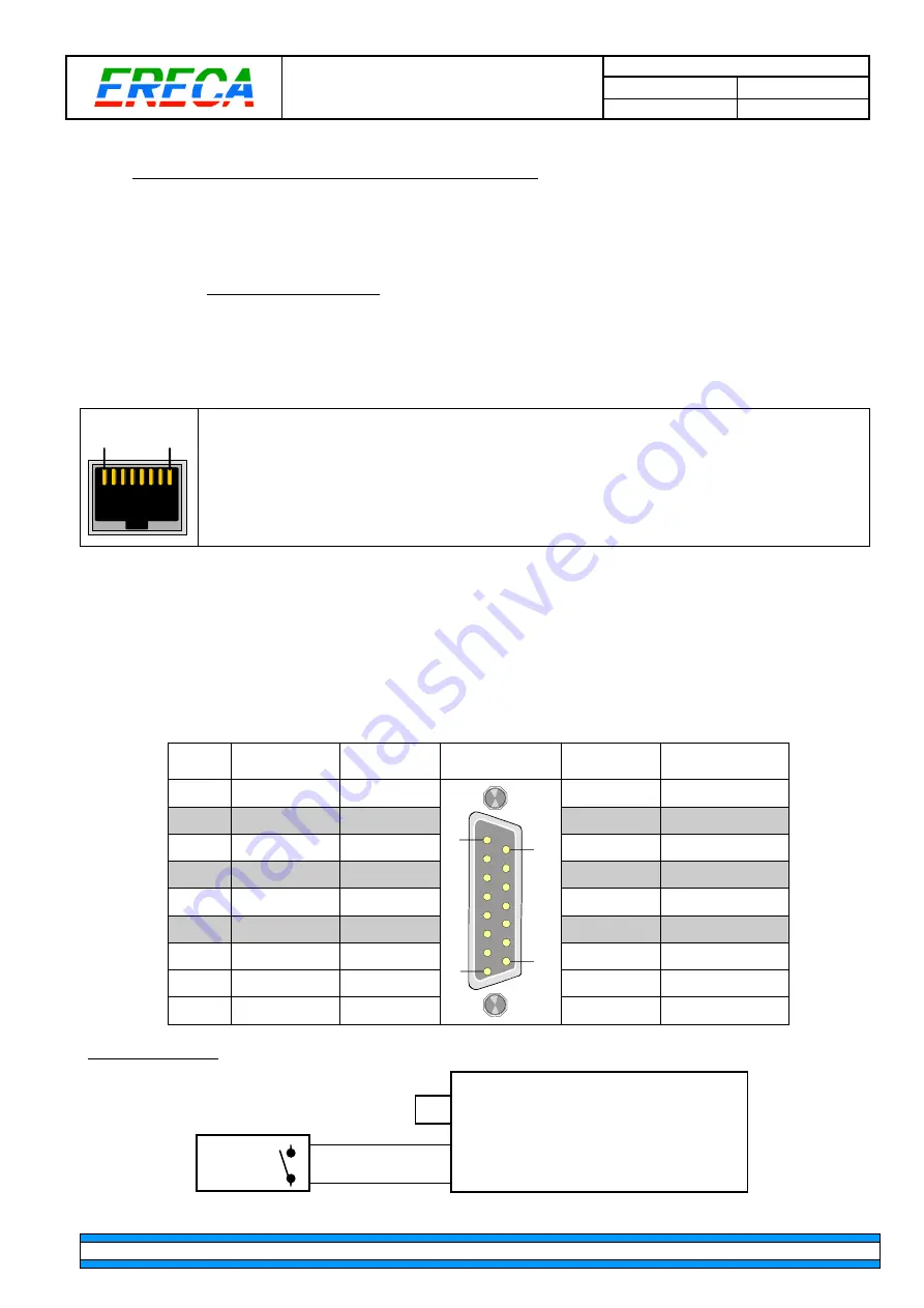
are shared with each Serial signal transmission RJ 45 terminal, labeled "Serial/Gpio". These
inputs are protected by an opto-coupler but are not floating; a grounding on the input pin triggers the GP-IN.
1
8
1: GND
2: GP IN
3: RX RS 422 – or RX RS 232
4: TX RS 422 – or TX RS 232
5: TX RS 422 +
6: RX RS 422 +
7: GP OUT
8: GP OUT
Inputs 3 to 8
are on one D-SUB 15 terminal female socket. Inputs are independent and electrically isolated
by opto-couplers. Each input is non-polarised and feature an automatic 5mA current limitation working with
an input voltage of 5 to 24 volts. The wiring polarity does not matter in this case.
Ground and power pins are available on the connector to ease interfacing with others machines especially if
a dry contact, open connector or ground closure supplies the information.
The 12 volts output of the Stage Racer 2 is protected against external short circuit by an internal 100mA
resettable fuse (polyswitch) common to the GPI and GPO sockets.
GP IN
N°
SIGNAL
Socket
contact
D SUB 15
GP IN
Socket
contact
SIGNAL
3
GP IN 3a
1
1
9
8
15
9
GP IN 3b
4
GP IN 4a
2
10
GP IN 4b
5
GP IN 5a
3
11
GP IN 5b
6
GP IN 6a
4
12
GP IN 6b
7
GP IN 7a
5
13
GP IN 7b
8
GP IN 8a
6
14
GP IN 8b
GND (0V)
7
15
+ 12V 100 mA
GND (0V)
8
Example: GP IN 3 (with dry contact, ground closure, open collector drive).
GP OUT
STAGE RACER 2
GP IN D SUB 15 terminal IN 3
9
1
0 V
+12V
7
15


