4 Setup and Mains Connection
14
ergoselect 4 / 5
1
2
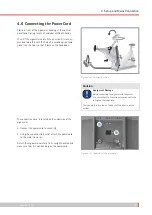
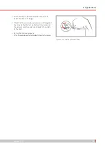
Figure 4 – 10: Connecting the power cord
1
Power input
2
Strain relief
Note
Disconnection from Power Supply
Pressing the power switch or removing the power
cord disconnects the device from the power supply.
Removing the power cord results in a complete disconnection
of the device from the power supply (all poles).
Ensure that the power plug is readily accessible at all times.
4.7 Data Interfaces
The ergometers are prepared for a functional connection
with a PC or a medical electrical device (ME device) via USB
or serial interface.
Different connection cables are available to support different
communication modes (digital, analog, remote start, etc.).
All ergometers are equipped with a digital interface. (Spe-
cial adapters are needed for analog control or the remote
start capability. Please contact ergoline for these adapters.)
The connection cable is plugged into the 9-pole socket of
the connection panel (Port 1) or the USB port and secured
at the metal frame with an additional strain relief.
USB
Port 1
USB
Port 1
Figure 4 – 11: Connection to electrocardiograph / PC-based ECG
system
USB
PC connection via USB (virtual COM)
PORT 1 Digital connection (remote control from
PC or ECG recorder), connection for cable
adapter (analog int remote start)
Note
Connection Cables
Use only connection cables approved by ergoline.
A special PC driver software, which can be obtained
from ergoline, is required for operation via the USB port.
Summary of Contents for ergoselect 4
Page 1: ...ergoselect 4 5 Ergometer Operator s Manual 201000433000 Version 2021 06 01 Rev 04 English...
Page 2: ......
Page 95: ......


