4 Setup and Mains Connection
10
ergoselect 4 / 5
4 Setup and Mains Connection
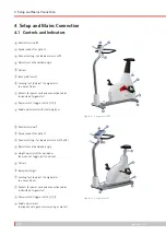
4.1 Controls and Indicators
1
Control terminal M
2
Speed readout for patient
3
Connectors (e.g., for blood pressure cuff)
4
Adjustment of handlebar angle
5
Castors
6
Base plate (small)
7
Leveling feet to adjust the ergometer
to uneven floors
8
Sockets for power cord and connection cables
(underside of ergometer)
9
Power switch (toggle switch [ I / 0 ])
10
Saddle adjustment with clamping lever
1
2
3
4
5
6
7
8
9
10
Figure 4 – 1: ergoselect 4 M
1
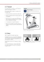
Control terminal T
2
Speed readout for patient
3
Connectors (e.g., for blood pressure cuff, SpO2)
4
Adjustment of handlebar angle
5
Height adjustment for handlebar
(by means of toggle switch, option)
6
Castors
7
Baseplate (large)
8
Leveling feet to adjust the ergometer
to uneven floors
9
Sockets for power cord and connection cables
(underside of ergometer)
10
Power switch (toggle switch [ I / 0 ])
11
Saddle adjustment
(optionally with gas pressure spring or motor)
1
2
3
4
11
6
7
8
9
10
5
Figure 4 – 2: ergoselect 5 T
Summary of Contents for ergoselect 4
Page 1: ...ergoselect 4 5 Ergometer Operator s Manual 201000433000 Version 2021 06 01 Rev 04 English...
Page 2: ......
Page 95: ......


