4 Setup and Mains Connection
ergoselect 4 / 5
15
4.8 Connecting ECG Leadwires
Plug the ECG leadwires (
R
,
N
,
L
) into the appropriate
sockets
1
in the control terminal, observing the color
codes on the leadwires and ergometer.
Warning
Connecting the leadwire to the wrong socket may
cause an incorrect ECG signal.
1
R N
L
Figure 4 – 12: ECG leadwire connections
Note
Only available with control terminal T.
4.9 Connecting the Blood Pressure Cuff
• Connect the microphone cable for blood pressure mea-
surement to the intended port
1
so that it clicks into
place.
• Slip the cuff tubing onto the fitting
2
and engage.
To disconnect, push back the connector's knurled
sleeve.
Artifacts must be avoided while the blood pressure is being
taken. They may be caused by patient movements during
the exercise test.
Therefore, do not forget to attach the cuff tubing to the
handlebar with the supplied Velcro tape:
• Open the large Velcro tape and wrap it around the
handlebar.
• Secure the cuff tubing with the small Velcro tape, but
do not exert pressure on the tubing.
1
2
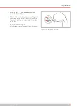
Figure 4 – 13: Blood pressure cuff connections
1
Microphone connection
2
Fitting for connection of cuff tubing
Figure 4 – 14: Velcro tape to secure the cuff tubing
Summary of Contents for ergoselect 4
Page 1: ...ergoselect 4 5 Ergometer Operator s Manual 201000433000 Version 2021 06 01 Rev 04 English...
Page 2: ......
Page 95: ......

