background image

 
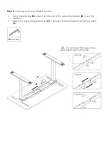
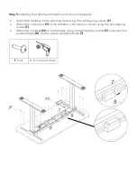
Step 5: 

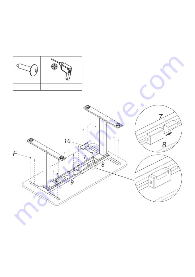
Installing the tabletop, handset, control box and adapter. 


Attach the tabletop to the standing desk using the self-tapping screws 

(F)


Attach the control box 

(9) 

to the tabletop in the position shown using the self-tapping 

screws 

(F)


Attach the handset 

(10)

 to the tabletop using the self-tapping screws 

(F)

 and insert the 

power adapter 

(8)

 into the power adapter bracket 

(7)


F

 (x14) 

Drill or impact driver 


Summary of Contents for ELDUAL2LGBA

Page 1: ...DUAL MOTOR 2 SECTION LEG STANDING DESK BLACK WHITE ELDUAL2LGWA ELDUAL2LGBA ...

Page 2: ......

Page 3: ...of in accordance with your local environmental legislation Do not dispose with general household waste Ensure this product is completely and correctly assembled before use Be familiar with all functions and program settings of the product before first use The desk will emit a slight noise caused by the V ribbed belt or brake system This is completely normal and will not affect the product s operat...

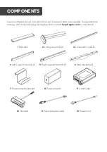
Page 4: ... check all packaging thoroughly then contact help Kogan com for assistance 1 Feet x2 2 Lifting column x2 3 Connection rod x2 4 Left support beam x2 5 Right support beam x2 6 Side bracket x2 7 Power adapter bracket 8 Power adapter 9 Control box 10 Handset 11 Power adapter cable 12 Power cord COMPONENTS ...

Page 5: ...Hardware list A M6 x4 B M6 x8 C M6 x8 D Self tapping screw x6 E Cable tie x6 F Self tapping screw x16 G Allen key ...

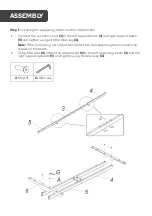
Page 6: ...t support beam 5 and tighten using with the Allen key G Note If the connecting rod cannot be inserted into the supporting beam loosen the screws on the beam Using M6 screw A attach the side bracket 6 to the left supporting beam 4 and the right supporting beam 5 and tighten using the Allen key G A M6 x4 G Allen key ASSEMBLY ...

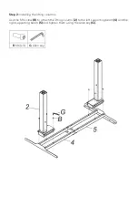
Page 7: ...p 2 Installing the lifting columns Use the M6 screw B to attach the lifting column 2 to the left supporting beam 4 and the right supporting beam 5 and tighten them using the Allen key G B M6 x8 G Allen key ...

Page 8: ...Step 3 Installing the feet Attach the feet 1 to the lifting column 2 using the M6 screws C and tighten using the Allen key G C M6 x8 G Allen key ...

Page 9: ...g the Allen key G adjust the distance of the supporting beams 4 to suit the tabletop Attach the power adapter bracket 7 in between the tabletop and supporting beam 4 G Allen key Loosen Tighten Adjust Do not adjust the supporting beam beyond this hole ...

Page 10: ...ng desk using the self tapping screws F Attach the control box 9 to the tabletop in the position shown using the self tapping screws F Attach the handset 10 to the tabletop using the self tapping screws F and insert the power adapter 8 into the power adapter bracket 7 F x14 Drill or impact driver ...

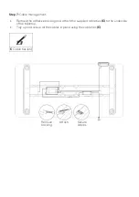
Page 11: ...n connectors to the control box 9 Connect the handset connector 10 to the control box 9 Connect the power adapter cable 11 to the control box 9 Connect the power adapter cable 11 to the power adapter 8 Connect the power cord 12 to the power adapter 8 Power adapter Handset Lifting columns ...

Page 12: ...ment Remove the adhesive backing and attach the supplied cable ties E to the underside of the tabletop Tidy up and secure all the cables in place using the cable ties E E Cable ties x6 Remove backing Attach Secure cables ...

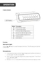
Page 13: ...ons Adjusting the height Press the or buttons to adjust the height of the desk The LED display will show the current height Memory function 1 Once the desk has been set to the desired height press the Memory button to save the height The LED will display 2 Press 1 2 or 3 to save the height to the corresponding button The LED will display or 3 Pressing 1 2 or 3 will automatically adjust the desk to...

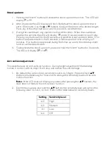
Page 14: ...during the follow up alarm the stand up alarm function will be deactivated 4 To deactivate the stand up alarm press and hold the Alarm button for 3 seconds The LED will display or Anti collision adjustment This desk features an anti collision function During height adjustment if the tabletop comes in contact with an object it will stop and reverse to avoid damage 1 By default the anti collision se...

Page 15: ...Column stage 2 Rated voltage AC 100V 240V 50 60Hz Max weight capacity 100KG Height range 710 1200mm without tabletop Width range 1100 1700mm SPECIFICATIONS ...

Page 16: ... and wait for 18mins before re connecting the power Not enough up down height Press and hold the Memory and 3 buttons together until you hear two beeps This will restore factory settings LED displays or Press and hold the button The desk will move into the lowest position and then reverses until it comes to a stop When the LED displays the height number release the button If the desk doesn t opera...

Page 17: ...NOTES ...

Page 18: ......

Page 19: ......

Page 20: ...tion We hope that this user guide has given you the assistance needed for a simple set up For the most up to date guide for your product as well as any additional assistance you may require head online to help kogan com ...

Reviews: