background image


Crack-Vac Model 100G Manual


Chapter 2 Safety 


©2020 by Crafco, Inc. All Rights Reserved 


Safety 2-4   

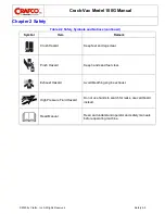
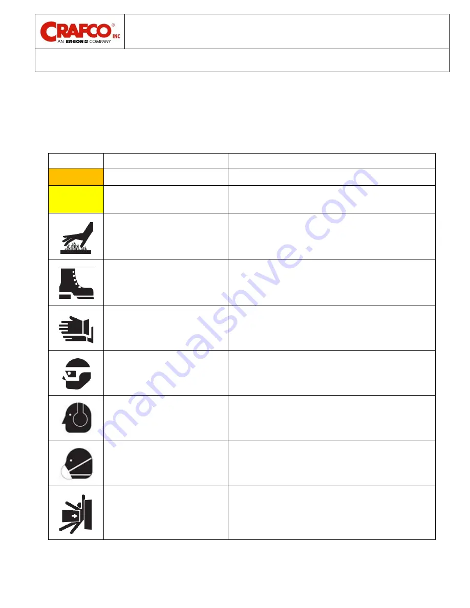
2.5 Safety Symbols and Notices 

Important safety symbols and notices are marked on the machine and in this manual. Failure to 
comply could result in equipment damage, operational malfunction, serious injury, or death. Please 
read and comply with all symbols and notices. The table below includes the most commonly used 
symbols and notices. 

Symbol 

Item 

Remarks 

WARNING 

Warning 

Refers to possible bodily injury or death. 

CAUTION 

Caution 

Refers to possible equipment damage or operational 
malfunction. 


Severe Burn Hazard 

Hot surfaces can cause severe burns. 


Protective Shoes 

Wear hard-soled work shoes. 


Protective Gloves 

Wear heat resistant gloves. 


Protective Face or Eye Wear 

Wear face shield or safety glasses. 


Hearing Protection 

Wear ear plugs or earmuffs. 


Dust Mask 

Wear a dust mask when appropriate. 


Body Crush Hazard 

Do not stand between trailer and hitch when hooking 
a trailer mounted Crack-Vac to a truck. 


Table 2-1 Safety Symbols and Notices 

Summary of Contents for 60800N

Page 1: ...CRACK VAC MODEL 100G Operator Parts Manual 26627N Revision O ...

Page 2: ...to this machine Machine S N ________________________________ Engine S N ________________________________ Blower S N _________________________________ Compressor Engine S N ______________________ Compressor S N _____________________________ ...

Page 3: ...Crack Vac Model 100G Manual Revisions Revision Date ...

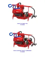
Page 4: ...CRACK VAC MODEL 100G with COMPRESSOR P N 60900N CRACK VAC MODEL 100G P N 60800N ...

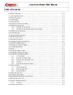
Page 5: ... Machine for Start Up 5 1 5 2 Starting the Blower Engine 5 5 5 3 Starting the Compressor Engine 5 6 5 4 Cold Weather Starting 5 7 5 5 Battery 5 7 5 6 Stopping the Blower Engine 5 7 5 7 Stopping the Compressor Engine 5 7 5 8 Compressor Operating Principles 5 8 Air Compressor 5 8 Oil Separation and Cooling 5 8 Minimum Pressure Check Valve 5 8 Filtration 5 8 Automatic Overheat Shut Down 5 8 5 9 Filte...

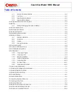
Page 6: ...System 6 8 6 11 Suction and Exhaust Hoses 6 8 6 12 EZ Glide Wand Assembly 6 8 6 13 Compressor 6 8 Compressor Engine 6 8 Compressor Oil 6 9 Blowdown Muffler 6 9 Pressure Relief Valve 6 10 Coalescing Filter 6 10 Air Intake Filter 6 11 Compressor Drive Belt 6 12 7 0 How to use a Multimeter 7 1 7 1 Checking DC Voltage with a Multimeter 7 1 7 2 Checking Resistance Ohms 7 1 7 3 Checking Wire Continuity ...

Page 7: ... 11 Truck Mounted Unit 5 17 Figure 6 1 Oil Viscosity Chart 6 1 Figure 6 2 Blowdown Muffler Relief Valve Coalescing Filter 6 11 Figure 6 3 Compressor Air Filter Housing 6 11 Figure 6 4 Replacing Compressor Drive Belt 6 12 Figure 7 1 Standard Multimeter 7 2 Figure 7 2 Clamp On Amp Meter Multimeter 7 2 Figure 8 1 Compressor Wiring Schematic 8 5 Figure 8 2 Hydraulic Power Pack Wiring Schematic 8 6 Fig...

Page 8: ... Operation 5 15 Table 5 17 Mounting CrackVac on a Truck or Trailer 5 17 Table 6 1 Maintenance Schedule 6 5 Table 6 2 Service Instructions 6 6 Table 6 3 General Maintenance Parts 6 6 Table 6 4 Changing Compressor Oil 6 9 Table 6 5 Testing the Blowdown Muffler 6 10 Table 6 6 Testing the Pressure Relief Valve 6 10 Table 6 7 Replacing the Coalescing Filter 6 10 Table 6 8 Replacing the Coalescing Filte...

Page 9: ...Crack Vac Model 100G Manual List of Tables Table 9 9 Compressor Assembly Parts List continued 9 16 ...

Page 10: ......

Page 11: ...cted in this manual Maintain your machine regularly as stated in this manual 1 1 How to use this manual This manual is formatted to start each new chapter on the right page There may be a blank page on the left page if the previous chapter ends on the right page If you are viewing this in a digital format PDF the following features are available 1 The Table of Contents List of Tables and List of F...

Page 12: ......

Page 13: ...ine Obey all CAUTION and WARNING signs posted on the machine Make sure an operator fully knows how to operate the machine before using the machine 2 2 Personal Safety Eye and ear protection devices along with a dust mask are required when operating the machine Wear long pants work gloves and heavy leather boots or shoes When cleaning cracks and joints near moving traffic always move in a direction...

Page 14: ...essor oil level and condition Do not add or change oil while the system is running The compressor operates anytime the engine is running Avoid contact with the compressor hoses oil cooler or engine during operation These items can become hot enough to cause major skin burns on contact Avoid the entrance of water into any part of the machine Shut down engine prior to refilling fuel tank Keep hands ...

Page 15: ... 3 2 4 California Proposition 65 The state of California currently maintains a list of chemicals that can cause cancer birth defects or other reproductive harm Your Crafco Inc equipment comes with the following warnings All Crafco Inc Equipment All Crafco Inc Equipment using a gasoline engine ...

Page 16: ...ls and notices Symbol Item Remarks WARNING Warning Refers to possible bodily injury or death CAUTION Caution Refers to possible equipment damage or operational malfunction Severe Burn Hazard Hot surfaces can cause severe burns Protective Shoes Wear hard soled work shoes Protective Gloves Wear heat resistant gloves Protective Face or Eye Wear Wear face shield or safety glasses Hearing Protection We...

Page 17: ...tices continued Symbol Item Remark Crush Hazard Keep feet and legs clear Pinch Hazard Keep hands and feet clear Exhaust Hazard Avoid breathing engine exhaust High Pressure Fluid Hazard Do not use hands to search for leaks use cardboard instead Read Manual Read and understand operator and safety manuals before operating machine ...

Page 18: ......

Page 19: ...d by accident alteration abuse improper lubrication maintenance normal wear or other cause beyond our control The warranty provided herein extends only to the repair and or replacement of those components on the equipment covered above and does not cover labor costs The warranty does not extend to incidental or consequential damages incurred as a result of any defect covered by this warranty All t...

Page 20: ...All engine warranties are covered through the engine manufacturer If you need information for a distributor in your area please contact us and we will direct you to the closest engine distributor All parts returned are tested and evaluated If the part has been modified in any way without prior consent from a Crafco Inc representative warranty is void Please follow the instructions stated below whe...

Page 21: ...ulti Chambered containing a high frequency absorption device to reduce excessive noise energy Engine Air Compressor Kohler Gasoline N A Model Command PRO CH 620 4 Cycle OHV Cast Iron Cylinder Liners Aluminum Block 19 HP 3600 RPM Air Compressor VMAC N A Model P190006 32 3 CFM 100 PSI 5000 RPM Prefilter Cyclonic Separator Primary Filter Pleated Spun Bonded Polyester Filter Element MERV 14 Rating 133...

Page 22: ......

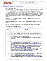
Page 23: ...ing any work on the equipment This will help prevent injuries 2 Check engine crankcase oil Add oil if low Refer to Engine Operators Manual 3 Fill engine gas tank with clean fresh unleaded gasoline See Fuel Recommendations in Engine Operators Manual 4 Check engine cooling air intake and external surfaces of engine Clean if dirty or obstructed 5 Check that the air cleaner components and all shrouds ...

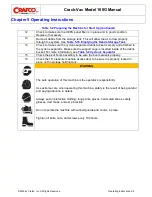
Page 24: ...he debris bucket For more information see Table 5 8 Cyclonic Separator 15 Check the pivot boom assembly to be sure the boom swivels properly 16 Check the 16 pressure manhole access door to be sure it is properly locked in place on the storage holding tank WARNING The safe operation of this machine is the operator s responsibility Use extreme care when operating this machine safety is the result of...

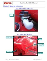
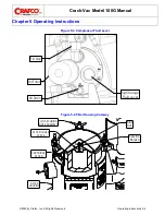
Page 25: ...g Instructions 2020 by Crafco Inc All Rights Reserved Operating Instructions 5 3 Fluid Fill Cap Sight Gauge Fluid Level Fill Cap Grease Fittings Relief Fittings Drain Plug Figure 5 1 Hydraulic Pump and Reservoir Figure 5 2 Rotary Blower Fluid Level ...

Page 26: ...o Inc All Rights Reserved Operating Instructions 5 4 Sight Gauge Fluid Level Oil Drain Fill Cap Oil Filter FILTER HOUSING CARTRIDGE FILTER FILTER COVER PLATE SEALING WASHER WING NUT LID SECURING NUT ASSEMBLY Figure 5 3 Compressor Fluid Level Figure 5 4 Filter Housing Cutaway ...

Page 27: ...ine to your local Kohler Service Engine Dealer Note If the engine develops sufficient speed to disengage the starter but does not keep running a false start the engine rotation must be allowed to come to a complete stop before attempting to restart the engine If the starter is engaged while the flywheel is rotating the starter pinion and flywheel ring gear may clash resulting in damage to the star...

Page 28: ... to disengage the starter but does not keep running a false start the engine rotation must be allowed to come to a complete stop before attempting to restart the engine If the starter is engaged while the flywheel is rotating the starter pinion and flywheel ring gear may clash resulting in damage to the starter CAUTION If the starter does not turn the engine over shut off starter immediately Do no...

Page 29: ...fast positions 2 Allow the engine to run a minimum of 15 seconds 3 Stop the engine by turning off the key switch 4 If not using the Crack Vac for longer periods turn off the fuel valve under the fuel tank to avoid flooding the carburetor when not in use 5 7 Stopping the Compressor Engine Step Action 1 Close the supply valve and allow the system to build to full pressure 2 Move the compressor enabl...

Page 30: ...oalescing filter is returned to the compressor via the PTFE scavenge tube A liquid to air cooler with electric fan maintains the operating temperature which reduces the temperature of the compressed air and increases the systems durability Minimum Pressure Check Valve The WHASP Tank has a built in minimum pressure check valve to maintain a minimum pressure of approximately 50 psi in the WHASP Tank...

Page 31: ...t A heavy duty plastic bucket liner can be inserted into the bucket with the support cage inserted into the plastic liner for easier disposal of the collected dust Secure the debris storage bucket to the cyclone with the lever lock ring See Figure 5 5 Debris Storage Bucket CAUTION DO NOT operate the machine without the bucket support cage inserted inside of the debris storage bucket Damage to the ...

Page 32: ...ach the debris storage bucket to the cyclone and secure with the lever lock ring 9 Restart the blower engine and continue vacuuming Plastic Liner Bucket Support Cage Lever Lock Ring Debris Storage Bucket Main Cartridge Filter The main cartridge filter and filter housing are vital components in this vacuuming system A clogged air filter can seriously affect the efficiency of the rotary air blower a...

Page 33: ...o not damage the filter If a vacuum is to be used use a standard shop vacuum cleaner with an attachment that has brushes on the end to prevent damaging the filter media CAUTION DO NOT bang or beat the filter on the ground or against any other object Doing so will damage the filter 5 Using compressed air 30 psi max blow through the pleats on the filter element from the inside out to prevent blindin...

Page 34: ...rystalline silica dust exposure Care should be taken to ensure that the filter will last for the longest possible amount of time The HEPA filter panel is not serviceable and must be replaced when it has reached the end of its useful life To get the maximum amount of use from the HEPA Filter The Cyclone Collection Bucket must not be allowed to fill past 7 8 full Dump the bucket regularly to keep fr...

Page 35: ...lip to prevent damaging the filter seal when pulling filter outward 5 To insert the filter make sure the filter push bar assembly is in the rearward position Place the leading edge of the filter on the support brackets and push the filter into the housing until it hits the stop brackets Note it may be necessary to slightly lift the trailing edge of the filter to allow it to go all the way into the...

Page 36: ...the storage tank by using the toggle switch located in the side frame at the front of the machine Lifting the toggle switch will raise the tank to the up position See Figure 5 8 Debris Storage Tank Switch 3 Once the dirt rocks and other debris have exited the tank use the toggle switch to lower the tank back to the down position WARNING Use caution not to pinch any part of the body when lowering t...

Page 37: ... be moved to the up position to allow debris to go under the brush and be vacuumed as opposed to the brush pushing the debris In all other instances the brush should be in the lowered position See Figure 5 10 Wand Routed Crack Brush Location 3 Attach the 25 foot lightweight vacuum hose to the overhead boom and secure the cam lock Attach the 25 foot air hose if equipped to the overhead boom Note Th...

Page 38: ... All Rights Reserved Operating Instructions 5 16 Wheel Spacers 5 total Remove a spacer to move the head closer to the ground For routed cracks remove two screws move holder to upper holes and replace screws Figure 5 9 Wand Wheel Spacers Figure 5 10 Wand Routed Crack Brush Location ...

Page 39: ...it 3 The hose boom and boom support will need to be turned and moved to keep the boom within the outside edges of the truck when in the stored travel position To move the boom support remove the three bolts and move the support to the opposite corner of the frame and reinstall the bolts See Figure 5 11 Truck Mounted Unit Note The machine is shipped with the boom in the correct orientation for trai...

Page 40: ......

Page 41: ...ge oil after every 100 hours of operation Change oil filter every 200 hours Use Crafco part number 31330 Refer to engine owner s manual for more information Oil Type Note Using oil other than service class SG or SH or extending oil change intervals longer than recommended can cause engine damage Refer to the Maintenance instructions in the engine owner s manual for detailed oil check oil change an...

Page 42: ...eling To minimize gum deposits in your fuel system and to ensure easy starting do not use gasoline left over from the previous season Do not add oil to the gasoline Do not over fill the fuel tank Leave room for the fuel to expand Fuel Type For best results use only clean fresh unleaded gasoline with a pump sticker octane rating of 87 or higher In countries using the Research method it should be 90...

Page 43: ...ive emission control system component Use only certified components when replacing an evaporative emission control system component 6 4 Battery Check charge condition Keep battery connections tight and clean Check the fluid level in battery regularly if it is not a sealed type Battery Recharging compressor battery When recharging do not use a battery charger rated for more than 8 AMP s If the batt...

Page 44: ...halation of exhaust gases can result in serious personal injury or death DO NOT use the air cleaner or exhaust elbow as a supporting step Damage of these and connecting parts might cause an exhaust leak WARNING Accidental Starts Before servicing the engine or equipment on the machine always disconnect the spark plug leads to prevent the engine from starting accidentally Ground the leads to prevent...

Page 45: ...cture s operating and maintenance instructions of the engine Blower Check oil level x Change oil x Grease end bearings x Blower V belts Check for wear damage and tension x Hydraulic Power Pack Check oil level x Change oil x Main Vacuum Filter Clean x Replace as needed or annually HEPA Filter Check x Replace as needed or annually Compressor Check oil level x Change oil and oil filter x x Replace bl...

Page 46: ... 31344 1 Secondary Air Cleaner 27HP 31345 1 Air Cleaner 19HP 44387 1 Foam Precleaner 19HP 31333 1 Vacuum Air Filter Main Cartridge Filter 60113 1 HEPA Filter Panel 60992N 3 V belt Blower 60862N 1 Serpentine Belt Compressor 60389N As Needed 5 Gallon Plastic Pail Liner 25 Count 60957N 1 Exhaust Muffler Blow Down Muffler Compressor 60993N 1 Safety Relief Valve Compressor 60994N 1 500 Hour Service Kit...

Page 47: ...n place a straight edge across the belt span Using a belt tension checker push the belt down midway between the pulleys and measure the deflection Recommended deflection is inch with a 6lb force applied Inspect the belts regularly for signs of cracking or fraying Replace the belts if they are showing signs of wear If one belt is showing signs of wear replace all the belts together CAUTION Over tig...

Page 48: ...l be caused to pump and or reservoir 6 11 Suction and Exhaust Hoses Be sure hoses are free of debris for efficient blower operation and damage to blower Inspect all hoses for damage make sure no hose is crushed kinked or has holes Replace any damaged hoses CAUTION Any blockages of the hoses prevent the vacuum from operating correctly 6 12 EZ Glide Wand Assembly Inspect the EZ Glide wand for damage...

Page 49: ...mpressor oil to the rubber gasket on the oil filter Spin the filter onto the threaded nipple until the gasket contacts the sealing surface on the tank then tighten the filter an additional to 1 turn to seat the gasket 8 Remove the fill cap and fill with compressor oil until it reaches the MAX mark approximately 1 gallon 4 liters of oil Replace the fill cap 9 Start the engine and check for oil leak...

Page 50: ...ng filter to prevent contamination 2 Remove the coalescing filter by turning it counterclockwise 3 Clean the gasket sealing surface and inspect it for damage The surface must be free of old gasket material and smooth to ensure a good seal 4 Apply a thin coat of compressor oil to the rubber gasket on the new coalescing filter 5 Spin the new filter onto the threaded nipple until the gasket contacts ...

Page 51: ...wn Muffler 200 psi Relief Valve Air Intake Filter Dust Ejector Valve Compressor Air Filter Housing Table 6 8 Replacing the Coalescing Filter continued Figure 6 2 Blowdown Muffler Relief Valve Coalescing Filter Inspect the air intake filter regularly Replace the filter if it is damaged or showing signs of wear Replace the filter every 500 hours of operation Inspect the dust ejector valve for damage...

Page 52: ...g of the belt is needed Replace the tensioner if it is showing signs of wear or damage Step Action WARNING Disconnect the battery cable to prevent accidental startups 1 Remove the 5 fasteners from the belt guard and remove the belt guard 2 Use a 3 8 drive to rotate the tensioner to remove tension from the belt and remove the belt 3 Replace the drive belt with a new one centering the belt over the ...

Page 53: ...h a Multimeter Connect the probes to the meter Set the range to a position that includes 12 volts or higher Touch the red probe to the positive side of accessory and black probe to ground If the item you are checking has a ground wire attached then use that ground or you can use the grounding stud on the battery tray assembly 7 2 Checking Resistance Ohms Connect probes to the meter Note When check...

Page 54: ...Crack Vac Model 100G Manual Chapter 7 How to use a Multimeter 2020 by Crafco Inc All Rights Reserved How to use a Multimeter 7 2 Figure 7 1 Standard Multimeter Figure 7 2 Clamp On Amp Meter Multimeter ...

Page 55: ...osition determine cause and repair or replace Engine air intake restricted Replace air filters Engine doesn t spin properly when cranking Starter problems Repair or replace starter See Engine Operators Manual Low battery Charge or replace battery Restriction from rotary blower Check for clogged hoses and or plumbing check for kinked hoses and remove any restrictions Check for dirty air filters Cle...

Page 56: ...s Manual Engine air intake restricted Replace filters Engine Stalls Compressor pressure set too high Lower compressor air pressure to 150 psi Operating at too high of an elevation Install high altitude carburetor kit See Engine Operators Manual Engine stalls when lowering throttle speed Compressor enable switch left in on position Switch to off before lowering speed Low engine oil Add oil Engine a...

Page 57: ...lace tube Blowdown muffler plugged or obstructed Replace muffler Blowdown valve failure Replace blowdown valve assembly Oil comes out of the blowdown muffler Operating angle more than 15 from horizontal Reduce operating angle Compressor oil overfilled Reduce oil level Check oil level with equipment on level ground Faulty blowdown shuttle valve Replace blowdown shuttle valve Blowdown valve failure ...

Page 58: ... to proper level Low Battery Charge or replace battery Faulty toggle switch Replace toggle switch Blown fuse Replace fuse Faulty solenoid Replace solenoid Faulty coil Replace Coil Plugged or faulty valve stem Clean or replace Cylinder function is spongy or moves with a jerking motion Air in the system Bleed air from the system Make sure the reservoir has a proper level of oil Table 8 4 Trouble Sho...

Page 59: ...5 30 86 OVERTEMP ALARM RELAY SOLDERED CONNECTION SOLDERED CONNECTION RED 5 12GA RED 4 12GA RED 1 RED 2 RED 2 RED 3 RED 3 ORG 1 ORG 1 BLK 1 BLK 1 BLK 1 BLK 1 BLK 1 BLK 2 ENGINE CONTROL RELAY AMBER WARNING LIGHT ALARM BUZZER RED BLK ORG 1 30 AMP FUSE 15 AMP FUSE SOLENOID UNLOADING VALVE 12 V BATTERY WHASP TANK NEG BATTERY CABLE NEG BATTERY CABLE POS BATTERY CABLE COOLER FAN MOTOR TEMP SWITCH Figure ...

Page 60: ...1 2 3 5 4 6 1 2 3 4 5 6 20 AMP FUSE 4 GA RED BATTERY CABLE TOGGLE SWITCH INSIDE VIEW OF HYDRAULIC VALVE POWER PACK HYDRAULIC MOTOR VALVE ASSEMBLY 12 VOLT BATTERY NOT ALL MODELS MAY HAVE THIS GROUND WIRE SOME ARE GROUNDED THROUGH THE BODY YELLOW PURPLE GREEN RED RED Figure 8 2 Hydraulic Power Pack Wiring Schematic ...

Page 61: ... are designed to show general shape and size of a part and the relationship that part has to other parts Actual size and shape of parts or components may differ or vary from the actual part or component 9 2 Ordering Crafco Parts Crafco distributors and Crafco Pavement Preservation Supply Centers are strategically located throughout the United States Parts can be ordered from your local Crafco dist...

Page 62: ...c All Rights Reserved Illustrated Parts List 9 2 9 3 CrackVac Parts List CrackVac Model 100G and Model 100G with compressor parts are identical with the exception of the compressor system 1 3 4 5 6 7 8 9 10 11 11 13 14 15 16 20 22 18 19 17 12 2 21 Figure 9 1 Right Front ISO View ...

Page 63: ... Support Mounting Arm 1 7 60094N Bracket Carbon Canister Mount Assembly 1 8 60392N Gas Tank Strap CrackVac 2 9 60950N Gas Tank Kit Dual Valve CrackVac 1 10 60855N Vacuum Boom Pivot Assembly 1 11 60915N Vacuum Hose Assembly 88 2 12 60159 Cam Groove Adapter Male X Female 7 13 60840N Cyclone Filter Assembly 1 14 60921N Clamp 3 1 2 SDBC 2 15 60920N Hose 3 1 2 I D Cyclone Outlet 1 16 60820N Filter Hous...

Page 64: ... Vac Model 100G Manual Chapter 9 Illustrated Parts List 2020 by Crafco Inc All Rights Reserved Illustrated Parts List 9 4 2 5 8 7 9 10 11 13 2 6 14 3 4 12 15 16 17 18 19 20 1 21 Figure 9 2 Left Rear ISO View ...

Page 65: ...h Wire Harness 1 60117 Hydraulic Power Pack Assembly no Wire Harness 1 7 60359N Lever Lock Ring 5 Gallon Pail 1 8 60357N 5 Gallon Black Steel Pail 1 9 60360N Modified 5 Gallon Pail Lid 1 10 60374N Bucket Hose Attachment Assembly 1 11 26092 Clamp Size 64 Gear 2 12 60373N Gasket Cyclone Filter 1 13 60918N Flex Hose 4 Cyclone to Bucket 1 14 32018 Covered Clamp 1 24 15 60854N Vibration Damping Mount 4...

Page 66: ...del 100G Manual Chapter 9 Illustrated Parts List 2020 by Crafco Inc All Rights Reserved Illustrated Parts List 9 6 2 3 5 6 7 8 23 22 19 1 20 24 9 10 4 4 11 12 13 14 15 16 17 18 16 5 21 25 26 Figure 9 3 Bottom View ...

Page 67: ...25952 3 1 2 U Bolt Muffler Clamp 6 10 60990N Vacuum Relief Valve 1 11 28007 1 1 2 Close Nipple 1 12 28360 2 x 1 1 2 Reducing Bushing 1 13 28259 3 x 2 x 3 Pipe Tee 1 14 60839N 3 x 4 Long TOE Nipple 2 15 60997N Hose Blower to HEPA Filter 1 16 60921N Clamp 3 1 2 SDBC 6 17 60991N Vacuum Gauge 30 to 0 HG 1 18 60960N HEPA Filter Housing Assembly 1 19 60998N Hose HEPA Filter to Cartridge Filter 1 20 2987...

Page 68: ...9 Illustrated Parts List 2020 by Crafco Inc All Rights Reserved Illustrated Parts List 9 8 9 4 Blower Drive Components Parts List 1 2 3 5 6 4 7 9 10 11 13 15 14 11 16 17 20 21 22 23 24 26 5 18 19 12 8 27 Figure 9 4 Blower Drive Components ...

Page 69: ...y Cable Ground 36 4GA 1 9 60861N Bracket Blower Belt Guard 1 10 60836N Blower Slide Plate CrackVac 1 11 28259 3 x 2 x 3 Pipe Tee 1 12 90858 3 8 16 X 4 All thread Bolt 2 13 28106 3 Pipe Nipple X 8 Length 1 14 28010 3 Closed Nipple 1 15 60151 Positive Displacement Rotary Air Blower 1 16 20914 27 HP Gas Engine 1 17 91344 Nipple Hose Combo King Fitting 1 18 25952 3 1 2 U Bolt Clamp 2 19 60917N Hose 3 ...

Page 70: ...SCRIPTION QTY Figure 9 5 1 60950N FUEL TANK KIT 1 2 31334 FUEL TANK CAP with TETHER 1 3 31319N ROV ROLL OVER VALVE with GROMMET KIT 1 4 60922N 1 4 ID LOW PERM FUEL HOSE 22 FT 5 60914N CARBON CANISTER 1 6 60094N BRACKET CARBON CANISTER MOUNT 1 7 60929N 1 4 HOSE CLAMP 8 8 60925N BARBED REDUCER 1 4 TO 3 16 MALE 1 9 60928N 3 16 HOSE CLAMP 2 10 60923N 3 16 ID LOW PERM FUEL HOSE 2 FT 11 60392N FUEL TANK...

Page 71: ...Crack Vac Model 100G Manual Chapter 9 Illustrated Parts List 2020 by Crafco Inc All Rights Reserved Illustrated Parts List 9 11 This page left blank on purpose ...

Page 72: ...l Chapter 9 Illustrated Parts List 2020 by Crafco Inc All Rights Reserved Illustrated Parts List 9 12 9 5 Suction Wand Assembly Parts List 14 13 12 11 10 9 8 7 5 4 3 2 1 15 16 19 20 6 11 21 17 18 Figure 9 6 Suction Wand Assembly ...

Page 73: ...dle Air Tube Assembly 1 6 57578 1 8 X 1 1 2 Cotter Pin 1 7 60233 1 4 90 Plastic Tube Fitting 3 8 60232 1 4 O D Plastic Tube 2 5 FT 9 60899N 1 4 Female Quick Connect 3 10 28534 1 2 13 ESNA Type Jam Nut 4 11 28674 1 2 SAE Flat Washer 4 12 60890N Square Head Weld Assembly 1 13 60896N Wheel Spacer 20 14 60897N 5 Swivel Caster 4 15 60595N Brush Seal Side 2 16 60593N Brush Holder Side 2 17 28176 Pipe Co...

Page 74: ... 27 31 30 25 25 28 29 32 33 31 33 32 34 35 37 38 41 40 41 42 43 44 45 47 48 36 10 18 15 29 46 49 Figure 9 7 Compressor Assembly 60802N Table 9 7 Compressor Assembly Parts List FIG ITEM PART NO DESCRIPTION QTY Figure 9 7 1 20958N Engine Kohler 19 HP Gas 1 2 24250 Hour Tach Meter 1 3 60351N Shroud Kohler Gas Engine 1 4 60346N Muffler Heat Shield 1 5 60345N Muffler 19 HP Kohler Engine 1 6 60398N 1 9 ...

Page 75: ...rive Pulley 1 16 60389N Serpentine Belt 1 17 60386N Belt Guard Compressor 1 18 60388N Spacer Belt Tensioner 1 19 60395N Support Angle 1 20 60939N Bracket Compressor Support 1 21 24037 Battery Strap with Buckle 4ft 1 22 37620 Battery 12V Group U1L 1 23 24003 Battery Box 1 24 60097N Tube Teflon PTFE 1 4 O D X 5 FT 1 25 60098N Tube Teflon PTFE 3 16 O D X 3 FT 1 26 60384N WHASP Tank VMAC 1 27 60095N D...

Page 76: ... AMP SPDT 2 40 60397N Compressor Controls Mounting Plate 1 41 60935N Light LED Amber Warning 1 42 50720 Boot Watertight Switch 1 43 60372N Decal Compressor Operation 1 44 60933N Sealed Connector Relay 2 45 60376N Sealed Toggle Switch 1 46 29845 Adapter 90 1 2 Tube X 1 2 Pipe 1 47 60934N Buzzer 12V Alarm 1 48 60371N Decal Compressor Alarm 1 49 26157 Decal Gas Exhaust Warning 1 50 20948 Battery Cabl...

Page 77: ......

Page 78: ... 2020 Crafco Inc ...

Reviews: