15(42)
Datum/Date
Rev
Dokumentnr/Documentnr
Uppgjord/Prepared
Dokansv/Godkänd - Doc respons/Approved
Kontr/Checked
Tillhör/Referens-File/Reference
1999-07-15
F
1545-ASB 150 02 Uen
FAULT TRACING DESCRIPTION
Faktaansvarig - Subject responsible
2.3
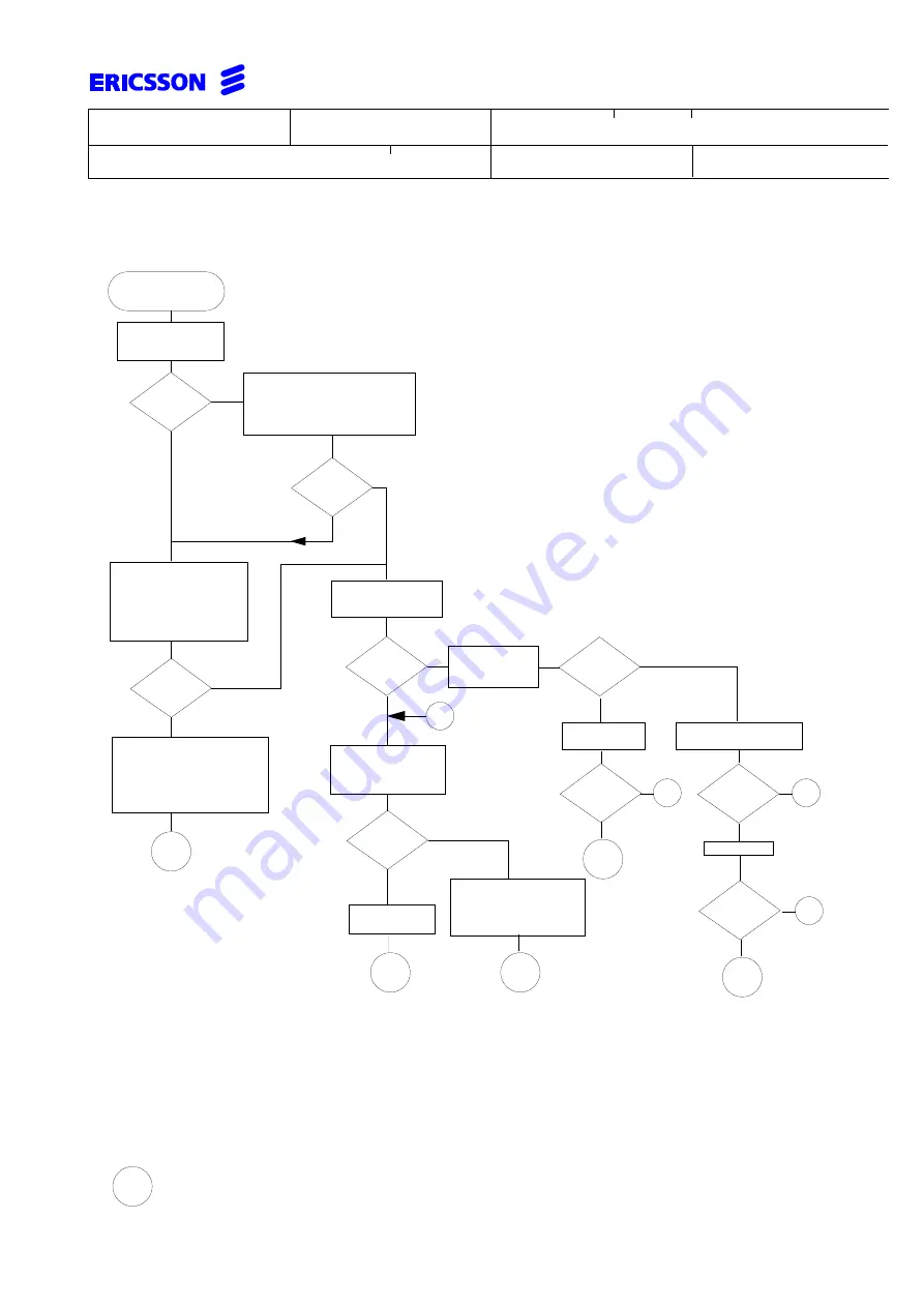
Flow chart: No possibility to make calls in PBX
Remove board after board in
cabinet and measure voltages
on the backplane. Replace
board causing the wrong volta-
ge(s). If the boards are not the
cause replace the back plane.
Verify that the exchange is
supplied with power. Check
48VDC/36VAC supply, the
cabling and if the voltages
are present on the back-
plane. (see point 4.7).
Remove front cover
on cabinet containing
the CPU-D.
Insert cold start strap and remove it
immediately. Does the red LED
(above cold start strap) light indica-
ting a cold start and extinguishes
when strap is removed.
Check all revision
states
(see point 4.15).
Check available (free) re-
sources (see point 4.11).
Update to latest
revision state.
Configure
mini-PBX
comprising one cabinet
and CPU-D.
Connect RASC.
Continue by increasing size
of PBX with one device
board at a time. Replace
boards that malfunction.
Replace CPU-D
and restart PBX.
START
Y
N
All LEDs
extinguished?
Y
N
Correct?
Connect
to
RASC.
Verify proper commu-
nication parameters
Y
N
Connection
successful?
Y
N
Power ok?
AA
Y
N
Valid
states?
revision
N
Resources
available?
Y
N
Correct?
Y
N
Fault
remains?
AA
N
Fault
remains?
AA
Restart PBX
AA
AA
AA
=
Go to " Completion of service" on page 31
1
1
Y
1
Y
1


